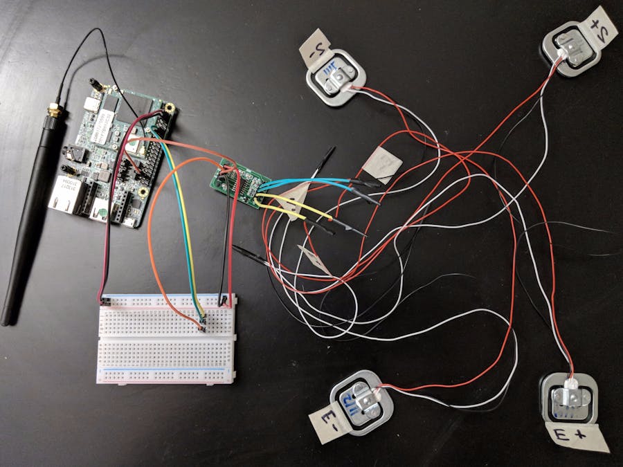
I set out to build a simple scale to determine the weight and thereby estimated volume of a keg in a kegerator. After a couple of nights mulling the hardware options and reading about similar project built with Arduino I got the impression this would be a quick project. Narrator: This would not be a quick project.
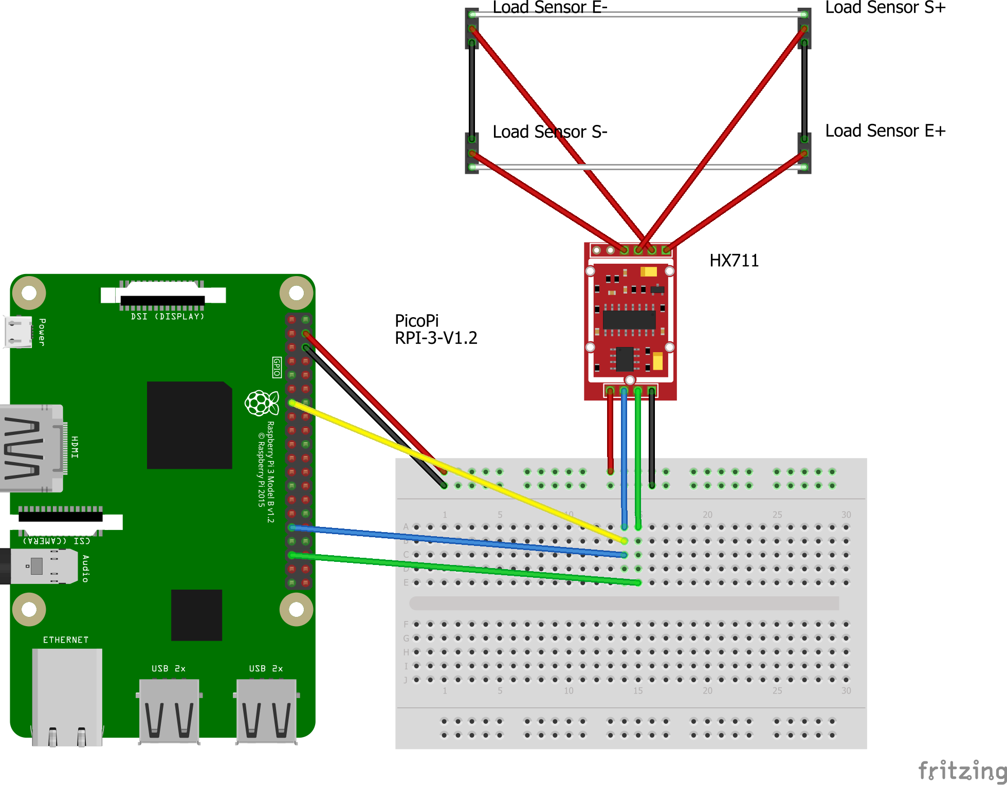
Hardware ChoicesFirst: the most fateful decision. I chose the HX711. This chip is common among projects converting some set of load cells into a functioning weigh scale. Most applications were built with a small Arduino, this chip and a set of 4 load cells arranged in a wheatstone bridge. See the fritzing diagram for how to wire that up.
Half bridge load cells were an obvious choice. They're readily available and what every other weigh scale uses to get a measurement.
Reading Data from the HX711The datasheet for the HX711 contains an simplified reference implementation.
Essentially the process of reading data from this follows a simple pattern and you only need worry about a clock pin and a data out pin.
Waking the device: When the device is asleep the data out will read HIGH. Set the clock pin to LOW and the data out will fall to LOW when the device is ready to be read.
Reading from the device: Once the data out is reads low, you have to send a pulse on the clock pin (think HIGH, then LOW) then a bit of data will available on the data out pin. High = 1, Low = 0. Do this 24 times and you've got your 24 bits of precision. Then one to three more pulses to set the gain.
Sleeping the device: Simply set the clock pin to HIGH, the data out should return to high.
Where this becomes difficult: If your pulse is HIGH for longer than 60 microseconds then the device will go to sleep and you have to start all over again. My HX711 was hard wired to 10 samples per second. So my device has a 100 milliseconds window to finish a read operation or you have to start over. The reference implementation has an option for 80 samples per second, see the datasheet for details.
Attempt 1: Pure GPIOMy original implementation of the driver for this was similar to the Arduino implementations. Use GPIO and set the pins as described and read the data. The GPIO pins couldn't be toggled from LOW to HIGH to LOW to perform the pulse operation in quicker than 2 milliseconds and that was rare. So this method wouldn't work. But it did reliably sleep and wake the device.
Attempt 2: PWM + GPIOAfter searching for a while I stumbled across a thread somewhere that suggested using PWM (Pulse Width Modulation) for the clock pin. PWM sends a high and low cycle. Duty is the percent of the cycle that's high (and it starts high). Hertz is the cycles per second. This was very unreliable with waking and sleeping the device. In theory you can set a 100% duty and a long cycle to keep the device asleep but the 0% cycle of waking the device was prone to error as the voltage had to go low then high then low again. This COULD be triggering another sleep or the first pulse in a data read depending on how quickly the operation happened. At this point the need for an Oscilloscope to verify my driver code was becoming obvious.
Attempt 3: SPI + GPIOAnother random forum thread idea. SPI (Serial Peripheral Interface) allows bytes to be sent and received. In theory if you use the MISO pin as our clock pin you could send a bit at just the right bit rate to get the exact duration you'd like. Great idea but this apparently uses a 5v, 2.5v and 0v to transmit. The HX711 is a 3.3v device so this was dead end idea. I'm sure someone could do some hacking here to get the voltage right but it was out of my skill range.
Attempt 4: GPIO/PWM + GPIOFinal attempt. Connect the GPIO and PWM to the clock pin. In my code I refer to this as the "Hybrid" solution. The idea here was to use the GPIO for the wake/sleep function which it was best for and to use PWM for the pulse operation. I was quite optimistic this would work but readings were never truly stable.
DataMy data seemed random from attempt 4 so I wanted to verify it. In theory if you read N times from the data out pin before the next pulse the value should be consistent. I logged 9 reads for every pulse and put it in a spreadsheet. If we're reading data correctly every row should have 9 true or 9 false values. While I got some consistent FALSE readings there are 0 consistent TRUE readings.
Verify the Wiring?I used a multimeter to verify the changes to force on the load cells was changing the voltage in a stable predictable way. So the analog data was being fed to the HX711 correctly.
ConclusionDon't use the HX711 with an Android Things device. I'm going to try another ADC that uses an actual SPI or I2C interface. This will be an increase in price at a decrease in accuracy but you should have a better chance at getting this to work.


_3u05Tpwasz.png?auto=compress%2Cformat&w=40&h=40&fit=fillmax&bg=fff&dpr=2)

Comments
Please log in or sign up to comment.