Wildlife monitoring is essential for keeping track of animal movement patterns, habitat utilization, population demographics, snaring and poaching incidents and breakouts. By conserving wildlife, we're ensuring that future generations can enjoy our natural world and the incredible species that live within it. To help protect wildlife, it's important to understand how species interact within their ecosystems, and how they're affected by environmental and human influences.
Animal tracking data helps us understand how individuals and populations move within local areas, migrate across oceans and continents and evolve across generations.
The aim of this project is to build a wildlife monitoring system. The project is named Wild AnImal Tracker in short WAiT. As its name, the sensor node WAiT for the movement of Wild Animal and Track its movement as soon as it is detected. The system can be implemented in National Parks, Forest and human habitation areas near forest where animal tracking is required.
I felt the need of this system very much. Once upon a time in 2003, I visited a national park in India. There I wanted to see the Tiger but very rarely I could see the tiger and I have to wait for longer time to see it as there was no system right then to identify the place where the Tiger is seen an notify so that I could go and see. This happen to many visitors who could not even see the Tiger during their visit to national parks. If I can implement my system in different suspected areas where Tiger could be seen, the system can report as soon as it is seen to control office so that visitors/tourists can immediately be moved to the place on safari to have a glimpse of the beautiful animal. This is only one example. This system can be very useful, for researchers who are studying wild animals. The system can also be implemented in the villages or human habitant area near forests so that people are aware of the wild animal activities and take precautionary steps to avoid any human-animal conflict.
How System Works?The working of this system is illustrated in following figure.
The sensor node which is capable of capturing the image and classify image WAiT in deep sleep for an event to occur. The event occur when the PIR motion sensor detect any animal activity. When this event occur, the sensor node which is in deep sleep mode wakes up and capture the image and classify the image with the help of tinyML model. It then connect to web server and upload the data and goes back to sleep again. The data is uploaded to web server can be seen by the user of the application. The system also send an e-mail alert.
PrerequisiteBefore you begin please setup and test ESP32 CAM by following instructions given in the tutorials below:
- Installing the ESP32 Board in Arduino IDE (Windows, Mac OS X, Linux)
- ESP32-CAM Video Streaming and Face Recognition with Arduino IDE
Collect data using the default ESP32 CAM firmware CameraWebServer.ino. For building the model I have collected the images of lion and zebra as following. The following figure shows that I have used the web interface from CameraWebServer.ino to capture the images for the dataset.
Note: I have used my daughter's animal toys ;) for building this model. This is just for testing purpose as currently wild animal images for same camera configuration is not available. The model on real animal images needed to be build by capturing animalimages in real conditions. For this a sensor node needs to be build which can be deployed in real condition just to collect the animal images and upload itto web server. In this article I have already specified how such type of sensor node can be build. It is very important to capture animal images in real condition in order to get the model work accurately.
Login to Edge Impulse and create a project WILD_ANIMAL_TRACKER. Now go to data acquisition and then go to upload data section and upload the images by specifying the label. You can upload multiple images at once for single label. for example select all lion images and specify the lion label and click begin upload button.
After you have done uploading images. Go to dataacquisition again there you will see all uploaded image list.
Go to Impulse Design and create impulse with the settings shown in following figure and click save impulse button.
Note: carefully observe all the settings in figure.
Next, goto image tab, observe image data and click save parameters button.
Go to transfer learning tab, under Neural Network -> Neural network architecture choose MobileNetV2 0.05. To do this click on choose a different model.
And then select MobileNetV2 0.05.
It is important to choose MobileNetV2 0.05 as the ESP32 CAM has low resources. After this step click start training button. You will see output similar to following figure.
Now you can go to Live Classification tab to test how the model is working. To test choose the image you want to classify under Classify existing test sample and click on load sample button as in following figure.
you will see the result as following
You can also go to Model testing tab and click on Classify all button to test model on test data.
After you find everything to be working fine, go to Deployment tab, click on Arduino library and scroll down and then click on Build button. This would download the model as Arduino library.
The model which is build using Edge Impulse is highly efficient and accurate as it uses very less memory without compromising accuracy. Thanks to award winning EON compiler.
Finally the model can be deployed by clicking Build button.
To test the model on real sensor node (i.e. ESP32 CAM) you need to include this zip library to your Arduino IDE. Please follow the instructions given here. After you include the library, it must appear like following.
After this download ESP32-Cam-Edge-Impulse examples from official Edge Impulse repository. The ESP32-Cam-Edge-Impulse/Basic-Image-Classification/Basic-Image-Classification.ino example will be used to test our model directly on ESP32 CAM.
Now open up the sketch Basic-Image-Classification.ino in Arduino and make sure to include the header file for the library which have created above using Edge Impulse. You must include the header file of your own model. You can locate it in the Arduino/libraries/Wild_Animal_Tracker_inferencing/src/Wild_Animal_Tracker_inferencing.h folder.
You have to use the same name for the header file as in the library folder.
Now uncomment the lines as shown in following figure for the board which we are using.
Now provide your WiFi settings in the code.
To upload the sketch enable settings as shown in following figure.
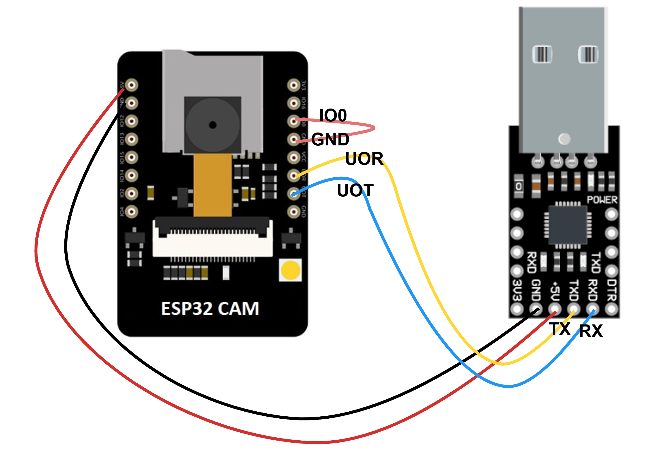
Now you need to connect your ESP32 CAM using USB to TTL module as shown in following diagram.
Note: don't forget to short the IO0 pin and GND pin on ESP32 CAM to enable uploading.
After connecting your board to computer, press reset button on back side of your ESP32 CAM, compile and upload code in Arduino. Make sure that correct PORT is available.
After uploading the code first remove the cable from IO0 pin and GND pin and push the reset button on ESP32 CAM. Now open the serial terminal there you will see IP address. Open web browser and use the IP address from serial terminal to capture the image. When the image is captured you will see the classification result in serial terminal of Arduino ide.
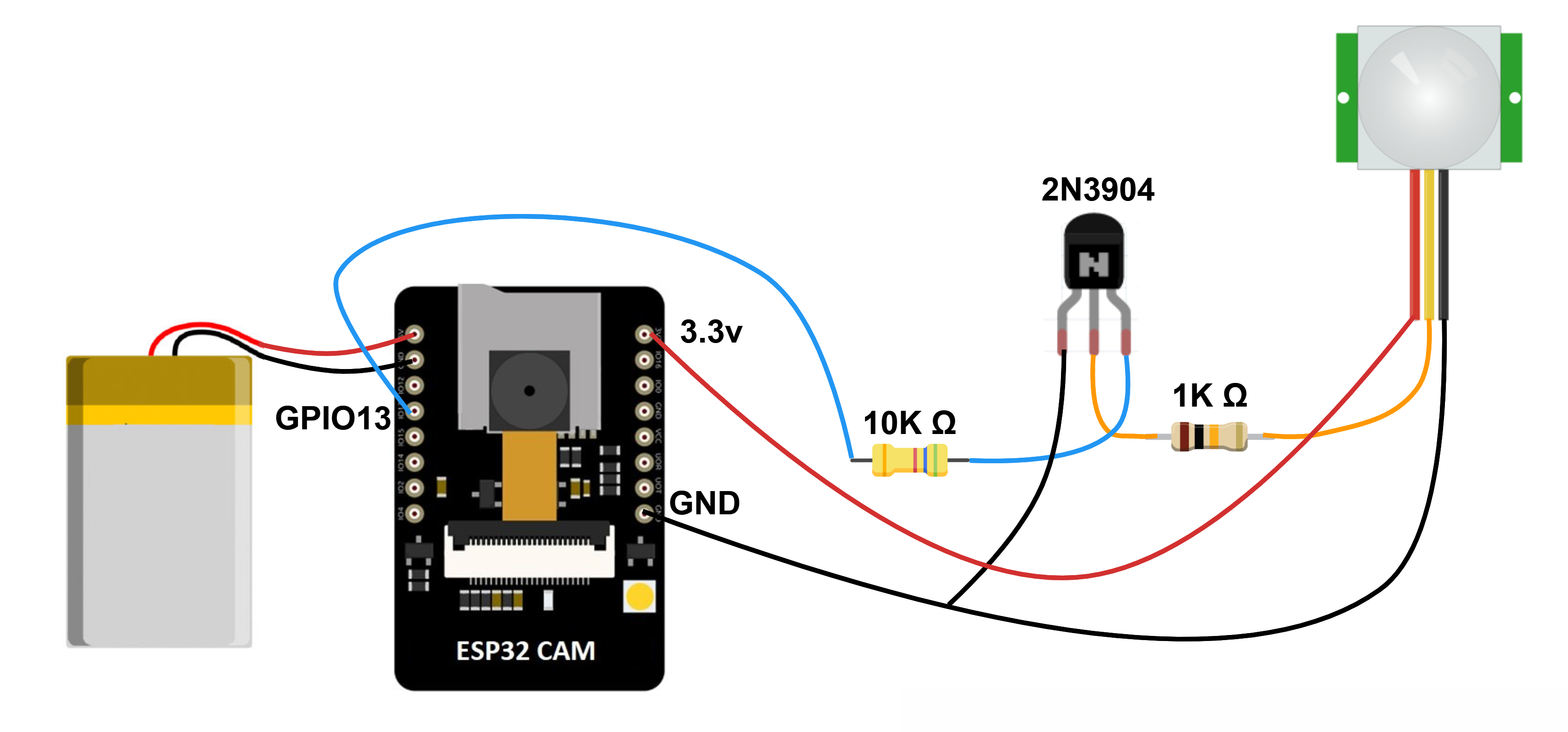
The next step is to upload the code of the firmware built for this project. (Short the pins and push reset button before uploading) First upload the Wild_Animal_Tracker_Firmware.ino firmware provided with this project. Disconnect your board, remove all cables and make circuit as illustrated in following figure.
Note: If you do not have the battery then you can use USB to TTL module to power up the ESP32 CAM. Only connect 5v and GND pin of USB to TTL module to 5v and GND pins ESP32 CAM. Other connections are not required.
In the code, the following statement includes the ML model which we have built using Edge Impulse
#include <Wild_Animal_Tracker_inferencing.h>I have declared following variables
char animal[20];
const int pir_sensor = 13;
Variable animal store the result of classification and PIR sensor is connected to pin 13 of ESP32 CAM.
The classify() function does the inferencing. In this function the inferencing result is stored in animal variable using following code.
if(result.classification[ix].value > 0.50000)
      strcpy(animal, result.classification[ix].label);
In the classify() function, a call to send_data_webserver() function is made which send the data to web server.
send_data_webserver(animal);The send_data_webserver() function accepts one parameter which is the output of the inferencing i.e. the animal detected. This function connects to the page on webserver and post the data. Change the IP address 192.168.157.130 to your own IP address.
void send_data_webserver(char animal[20]){
  //Open a connection to the server
      HTTPClient http;
      http.begin("http://192.168.157.130/wild_animal_tracker/upload.php");
      http.addHeader("Content-Type", "application/x-www-form-urlencoded");
    //format your POST request.
      int httpResponseCode = http.POST("animal=" + String(animal));

      if (httpResponseCode >0){
          //check for a return code - This is more for debugging.
        String response = http.getString();
        Serial.println(httpResponseCode);
        Serial.println(response);
      }
      else{
        Serial.print("Error on sending post");
        Serial.println(httpResponseCode);
      }
    //closde the HTTP request.
      http.end();
}
I have defined function run_classifier() which is being called in the setup() function. The run_classifier() function actually make a call to the classifier() function which does the inferencing and make a call to send_data_webserver() function which publishes the data to web server. The functions are invoked in following sequence run_classifier()-->classifier() --->send_data_webserver(). Following is the code for run_classifier().
void run_classifier(){
    fb = esp_camera_fb_get();
    if (!fb) {
        Serial.println("Camera capture failed");
    }
    classify();
    esp_camera_fb_return(fb);
}
finally in the setup() function I have enabled the external wakeup with the help of following code
esp_sleep_enable_ext0_wakeup(GPIO_NUM_13, 1);This external wakeup uses the input signals from PIR sensor connected on GPIO pin no. 13. So when the motion is detected, the ESP32 Wakes up, do inferencing, send data to web server and goes to deep sleep again. In this way we can save a lot of battery power. The sensor only perform processing when it is required otherwise it is in deep sleep mode rest of the time.
It has already been well researched that ESP32 in Deep Sleep consumes very less energy and can be utilized to save a lot of battery energy and make the sensor node run for longer period of time on battery. The following link describes the Deep Sleep feature of ESP32 board.
ESP32 Deep Sleep with Arduino IDE and Wake Up Sources
The Deep Sleep Mode is for Low Power Consumption: In deep sleep mode, the CPU, most of the RAM and all the digital peripherals are powered off. The only parts of the chip that remains powered on are: RTC controller, RTC peripherals (including ULP co-processor), and RTC memories (slow and fast). The chip consumes around 0.15 mA (if ULP co-processor is powered on) to 10µA.
To enable Deep Sleep the following function is called.
esp_deep_sleep_start();The esp_deep_sleep_start() function sends the ESP32 to Deep Sleep. Also take a note that before calling esp_deep_sleep_start() function I have called WiFi.disconnect() function as it is important to disconnect WiFi connection before going to sleep mode otherwise on wakeup ESP32 won't connect to WiFi.
Now the next step is to install a web server. Web Server for this project can be used in two ways
- Webserver on local computer
- Webserver on hosting space on Internet
If you buy a hosting space, you do not need to install the web server. You just need to upload the code to the webserver provided with this project. If you are planning to install the webserver on local computer then I prefer XAMPP web server.
Download the XAMPP server on your local computer and then navigate to htdocs folder in the webservers root directory and copy paste the entire wild_animal_tracker folder. This is your web application. It contains the files and directories as shown in following figure.
Open the DBController.php file and change the following database settings
private $host = "localhost";
private $user = "root";
private $password = "";
private $database = "test";
Remember to create a database named 'test' using phpmyadmin module once you install XAMPP webserver and create following table which will store the data.
CREATE TABLE wild_animal_data ( id INT(6) UNSIGNED AUTO_INCREMENT PRIMARY KEY, animal_detected VARCHAR(30) NOT NULL, reading_time TIMESTAMP DEFAULT CURRENT_TIMESTAMP ON UPDATE CURRENT_TIMESTAMP );DBController.php file contains all the functions to upload and retrieve the data. Once all the settings are done you can connect the sensor node and then open the web app in the browser using following URL.
http://localhost/wild_animal_tracker/display.htmlor
http://192.168.157.130/wild_animal_tracker/display.htmlRemember that 192.168.157.130 is the IP address of your system which you need to change. This same IP address is also used in Arduino code. The IP address is needed in case you are accessing the web app other than on the system where it is installed. on windows you can use ipconfig command and on Unix/Linux you can use ifconfig command to find the IP address of your system.
As the web application also sends email alert, the settings for sending and receiving emails should also be updated. Open upload.php file and update the settings for email in the sendAlert() function.
//This function sends an e-mail alert
function sendAlert($animal){
     $mail = new PHPMailer(true);        // Passing `true` enables exceptions
    date_default_timezone_set("Asia/Kolkata");
                $dateTime = date("Y-m-d H:i:s");
     try {
                    $mail = new PHPMailer;
                    $mail->isSMTP();
                    $mail->SMTPDebug = 2;
                    $mail->Host = "smtp.gmail.com";
                    $mail->Port = "587"; // typically 587
                    $mail->SMTPSecure = 'tls'; // ssl is depracated
                    $mail->SMTPAuth = true;
                    $mail->Username = "your_password";
                    $mail->Password = "your password";
                    $mail->setFrom("sender_email", "Wild Animal Tracker App");
                    $mail->addAddress("receipient_email", "receipient_name");
                    $mail->Subject = 'Alert! '.$animal.' has been detected';
                    $mail->msgHTML($animal. " has been detected at ". $dateTime);
                    $mail->AltBody = $animal. " has been detected at ". $dateTime;
                    //$mail->addAttachment('docs/brochure.pdf');

                    $mail->send();
             echo 'Message has been sent!';
            } catch (Exception $e) {
                                //error
                echo "error: ". $e;
     }
}
Change $mail->Host and $mail->Port according to your SMTP server if you are not using Gmail. Update $mail->Username = "your_password" and $mail->Password with your email login credentials. In $mail->setFrom() function update the email address of sender and in $mail->addAddress() function update the email address and name of recipient.
There is one more step that you need to take if you are using Gmail SMTP server. That is you need to allow Less Secure app in google otherwise web app could not send the email alert. You can enable it by visiting URL https://myaccount.google.com/security and login with your Gmail account.
Note: The less secure app settings are required only when using GMail SMTP server. If you have your own web server and hosting space you will usually get few e-mail accounts with you domain with SMPT settings. If you upload this web application on your own domain with SMTP settings and email address then this application run without specifying any security settings.Results
The following videos and figures shows the output of the system.
Video Explanation: The above video Sensor Node - Running Inference on EXTERNAL WAKEUP using PIR Sensor show the working of tinyML model. In the video first you see the image of zebra in the web application interface which was detected earlier. The sensor node is in sleep mode. In the video when I place my hand in front of PIR sensor, it means that the sensor has detected some animal. Now the ESP32 cam wakes up and captures the image of Lion that is placed in front of camera. The ESP32 than run the inference, classify the animal and upload the data on web application and go back to sleep again as you can see in serial terminal. The result is also changed on web application immediately that sensor has detected a Lion now and email alert is also sent.
The following image show the execution of tinyML model on serial terminal and the result is reflected in the web application.
The web application has different section to display information.
The web application dashboard currently display the image of the animal detected, date and time at which the animal is detected, recent 15 records from database in JSON format and frequency of top five animals detected. Currently the interface display static image of the animal. The real time image of animal can also be displayed which is under development.
The following image shows the alert sent on Gmail account.
This project can be used as very useful application in wild life monitoring which can assist in conducting research on animals when it is not possible for researchers to visit the location frequently. The researchers can conduct the research on animals in the applicable area. The location of the animal can be identified using the device id that is installed in the particular area. The idea is to give unique id to each device. This way we can reduce the extra workload of device by adding GPS sensor thus can save more power.
This project is highly customizable as other features can be easily added as per user requirement. The project can also be customized to upload real time image of animal. I am currently working on this feature. For example if lion is detected the sensor node will automatically upload the lion image on lion folder on webserver by creating another subfolder with date-time. The web interface is also under development which will allow to generate full report.
Due to budget constraint I have used ESP32 CAM board which has its own limitation. However I am planning to use Luxonis LUX-ESP32 and also to utilize Depth AI features of it which will make sensor node for this project more powerful and efficient. I am also planning to use LoRa network which will expand the connectivity of this project and can also be used to gather location data with low power feature since the LoRa consumes much low energy than WiFi. It has already been proven that LoRa can be utilized in forest environment. Adding solar powered battery is one another concern.


Comments
Please log in or sign up to comment.