The Arduino Gatekeeper is an IoT-connected authenticator for outdoor gates and doors (or anything else that can be monitored with reed switches). The first function of the device is to remotely monitor when gates are opened or closed and send immediate alerts to Windows 10 devices as well as uploading this data to the Windows Azure cloud for logging and analytics. This might be useful for people who have gates or doors that are not easily monitored, such as an unoccupied property or a gate far away from the main house.
In addition, the device can read RFID/NFC tags that are presented by people attempting to gain access to the area secured and transmit the user’s unique ID to a Windows 10 device for authorization. The recipient of the alert can then choose either to open the gate, which will retract the locking rods and allow the gate to be opened, or prevent the gate from being opened. Tags can be stored in the local microprocessor for recurring visitors. This is useful in cases where, for example, a gardener may need access to your backyard every week, but you would prefer not making them duplicate keys. You could also use this to allow neighbors or family access to your backyard to check on pets or water plants while you are away on vacation.
Here is a high-level overview of the Arduino code:
1. The module polls Virtual Shields and/or Azure for instructions until a RFID tag is scanned.
2. Once a tag has been scanned, the Arduino will check the internal database to determine if a preset action has been configured for the tag.
3. If the tag is recognized, and configured with access permissions, the servo will retract the locking bars and the door will be allowed to open.
4. This action will cause an event to be logged to Azure recording the tag ID and the date and time the gate was opened.
5. Once the reed switch detects the gate has been closed, it will re-lock the gate using the servos after a preset delay to allow for de-bouncing of the reed switch.
- A local bypass key switch can also be configured, but this depends on the security level the end-user desires.
- The locking rods controlled by servos can be replaced with some other device such as a Lockitron™ if the gate’s configuration allows for this (some gates do not have deadbolts, but rather a single handle with an integrated lock. The Lockitron (TM) can be used to replace deadbolts that are independent from the handle).
I was interested in making this project because there were often times where I wondered whether or not the back gate to my house was locked. Therefore, I thought that an IoT-connected device would be great to check on its status. However, I also thought that the gate could be made keyless at the same time, using an RFID card instead of a key. Control by a phone would also be another plus. Therefore, I came up with this idea to make a connected device that would help monitor the status of my gate in addition to providing keyless entry.
DescriptionAzure:
- Set up a free Azure account from Microsoft.
- Add a new Azure IoT Hub to serve as the endpoint. Take note of the hostname, shared access key, and shared access policy name. These are needed for connecting the microcontroller.
- Download the Microsoft Device Explorer and connect the microcontroller to the IoT Hub using the SAS authentication key.
- Mohan Palanisamy has a good tutorial here: MKR1000 Azure IoT Hub How-To
- This should take you up to these steps.
- Set up an Azure SQL Server by following the prompts after adding the service (the Free pricing tier should be sufficient).
- Set up a server name and note this. Also set up the server password.
- Go to the tools menu for the SQL server and select "Open Visual Studio" (Visual Studio should be installed by now; the Community edition is sufficient).
- Set up a new database and one table to store the data. Use the following T-SQL code to build the table.
CREATE TABLE [dbo].[Data1] (
[Id]       INT           IDENTITY (1, 1) NOT NULL,
[DeviceId] NVARCHAR (10) NOT NULL,
[Time]     NVARCHAR (50) NOT NULL,
[RFID]     VARCHAR (20)  NOT NULL,
[ID1]      NVARCHAR (50) NULL,
[Access]   NVARCHAR (30) NULL,
[Gate]     NVARCHAR (20) NULL,
CONSTRAINT [PK_DATA1] PRIMARY KEY CLUSTERED ([Id] ASC)
);
- Click on the update button to run the script on the SQL server.
- Create a new Stream Analysis job to read the data from IoT Hub and store it in the SQL database.
- Setup the IoT Hub as an input using the proper connection strings as set up earlier. Set up the SQL database and table as the output of the Stream Analysis job. Use the query code supplied below.
- Start the Streaming Job.
Windows Virtual Shields:
- For best results, download the Virtual Shields repository from GitHub
- Using the Shield.sln file, open the solution in Visual Studio and deploy it to the computer or phone following the instructions on the GitHub page.
Arduino:
- Install the necessary libraries for the Arduino IDE (version 1.6.7): WiFi101, Windows Virtual Shields, TimeLib by Paul Stoffrogen and/or Michael Margolis: GitHub Repo
- Compile and upload the code that is attached in the GitHub Repo under the Software section.
- Verify that the Arduino is connecting to WiFi and is successfully polling the IoT Hub through the Serial Monitor.
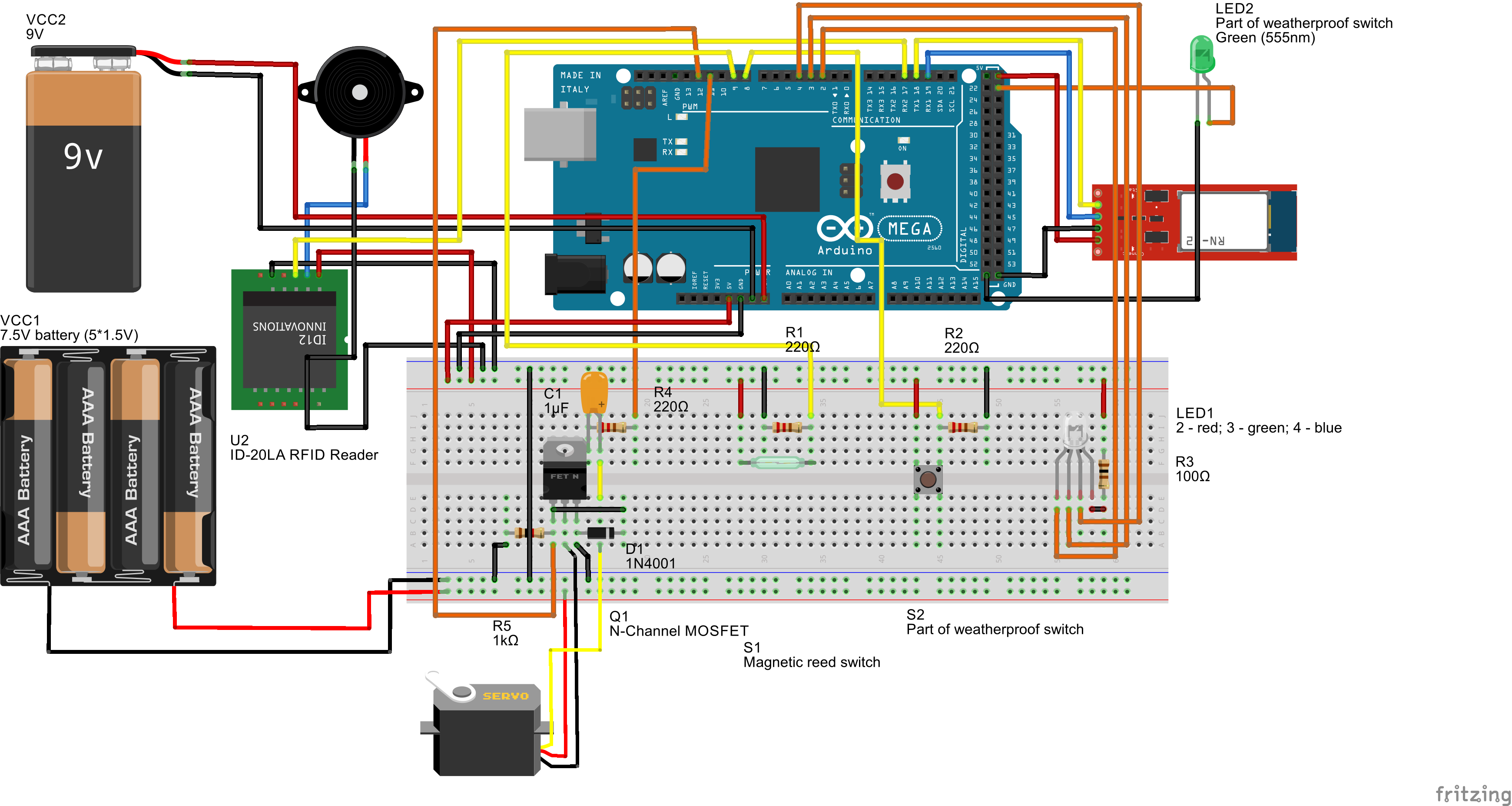
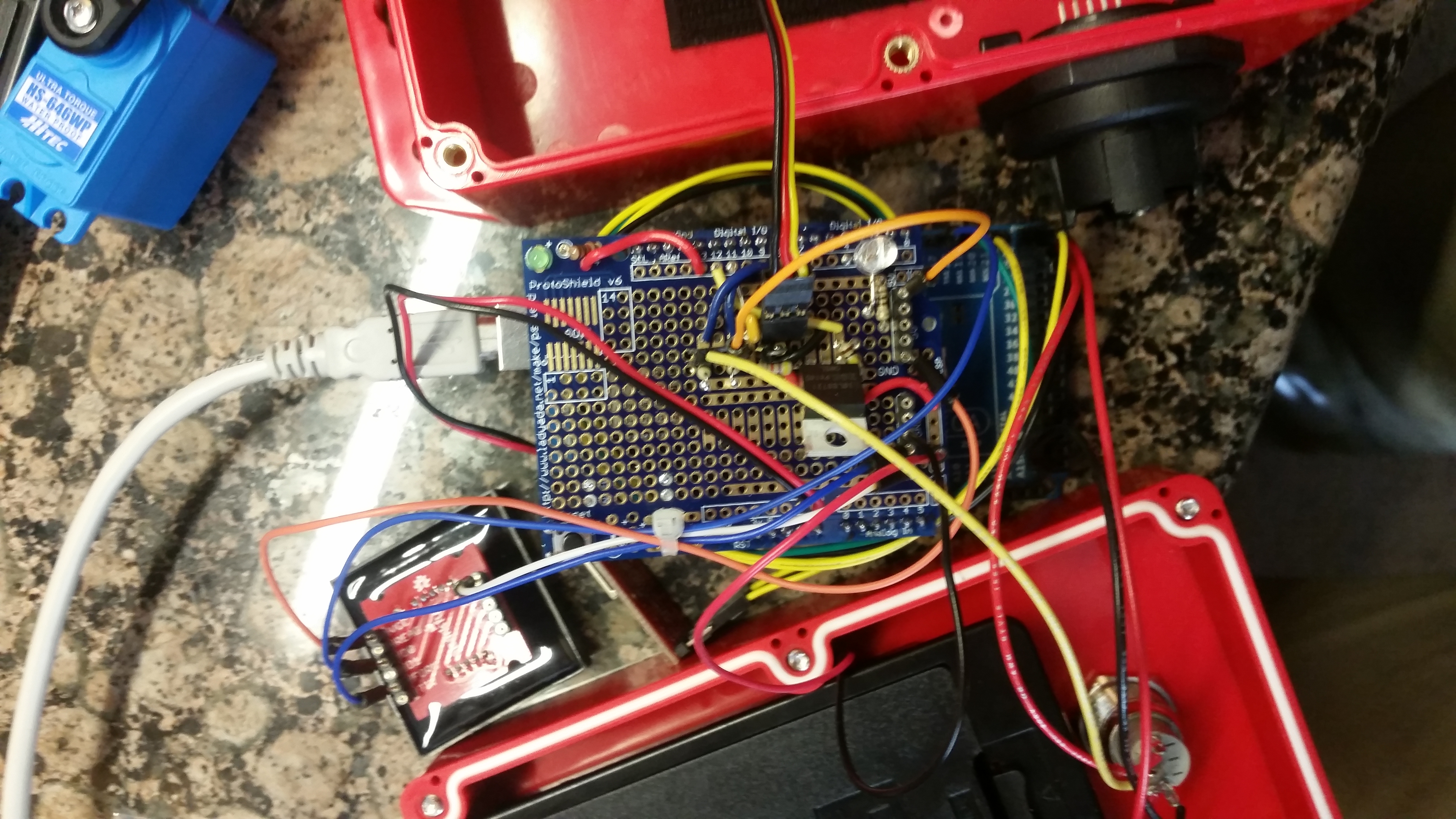
- Assemble either a breadboard or protoshield with the electrical diagram provided below.
- You can list your own RFID tag numbers in the RFID_method tab of the Arduino sketch. Add additional "if" statements for each RFID tag to be recognized.
- You can personalize the night light settings of the manual override button in the RTC_method tab under the "void digitalClockDisplay()" function by setting the sunset and sunrise hours.
Hardware:
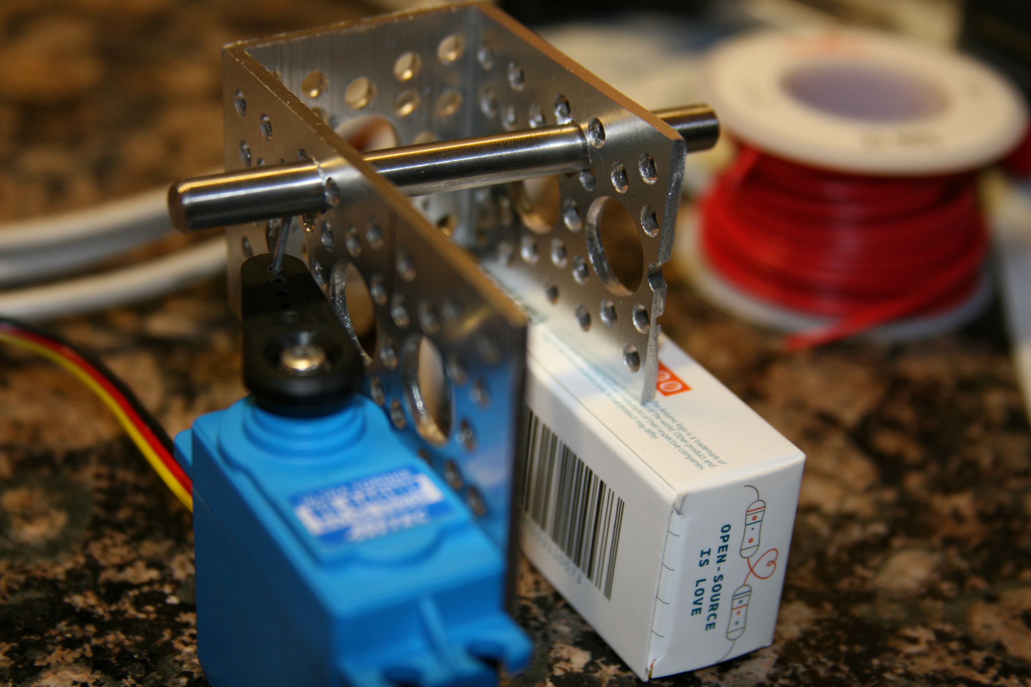
- Using a metal saw or equivalent, cut one unit (~1") off of the right-side of the stainless steel A-bracket from Sparkfun. This should allow the gate to open without the A-bracket moving against the stationary beam of the gate.
- Depending on the locking rod used, adjust the diameter of the holes for it to slide easily from a closed position to open position using a drill and drill bit.
- Attach the arm attachment to the servo.
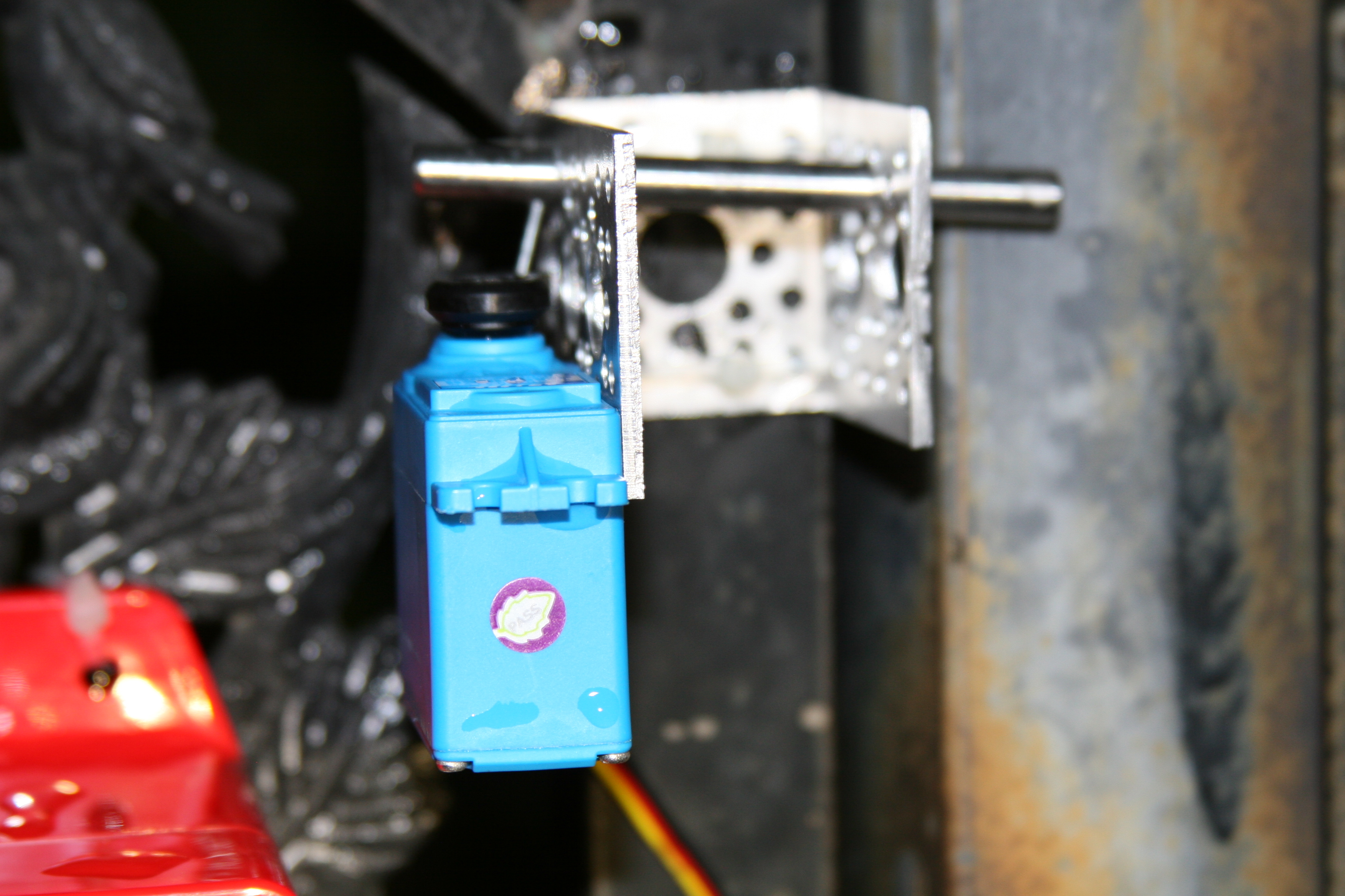
- Add a pin to the locking rod so that it can be controlled by the servo, which should be attached to the long side of the A-bracket.
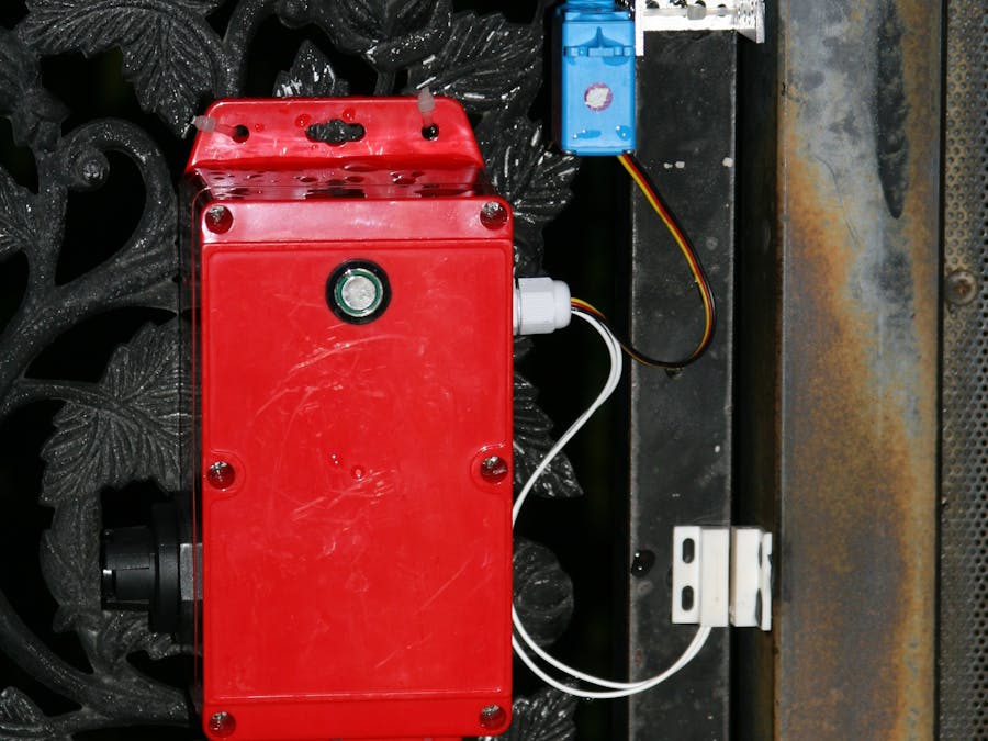
- Mount this assembly to the gate and pass the servo cables and magnetic switch wires through the cable gland on the enclosure.
Now you can turn on the Arduino by plugging in the batteries and try scanning an RFID tag that is authorized to access the gate. You can also connect to the Bluetooth module with the Windows Virtual Shield App and click on "Refresh" to see the splash screen.
You can test the operation of the servo using the manual override button. Using the manual override switch in the Virtual Shields application will also have the same effect. RFID tags that are scanned will appear in the center of the screen along with their authorization status. Any other status messages will also be reported on the screen. Manual override and RFID scans will generate events that are sent to the IoT Hub, processed by the Stream Analytics, and added to the SQL database.
OperationTo operate the Gatekeeper, you can either scan a RFID tag or use the physical or virtual override switches. It requires 5 AA batteries to power the servo and one 9V battery to power the logic circuits.
Depending on the material of the gate, the position of the RFID reader may have to be adjusted for optimal performance.
Below is a video describing the functions of the Gatekeeper:
Further Improvements
In the future, I would consider adding a switching voltage regulator (instead of the on-board linear one) to prolong the battery life of the unit. The battery life is relatively short because of the 9 volts being reduced to 5 volts with a linear regulator, releasing the extra energy as heat. In addition, it would simplify the device if just one power source could be used. In addition, I would get additional protection for the exposed locking system, since in the video, someone could easily pry open the servo lock from the outside of the gate. Bluetooth security would also be needed to prevent unauthorized electronic tampering with the system.
I would also like to pursue my original goal of using an online database of RFID tags to simplify remote administration of the Gatekeeper. This would eliminate the need to re-program the Gatekeeper each time a RFID tag needs to be added to the authorized list.
ConclusionMaking this project turned out to be very interesting and educational. I learned more about the various types of microcontrollers that Arduino offers and also about communicating with cloud services. I was excited to see the new interactions that the Microsoft Virtual Shields would enable humans and microcontrollers to have. The Virtual Shields made it very easy to receive and send information to and from the microcontroller. Azure integration was very useful as it was able to receive, categorize, and store information in a relatively easy manner. I hope that this project will help others create similar devices and further improve on the ideas I have developed. Finally, thank you to all of those who have contributed code for the libraries and example code for other functions, as well as my brother who proofread my code as these have further developed my coding skills.


_ZSyI6P3uFq.jpg?auto=compress%2Cformat&w=40&h=40&fit=min&dpr=2)
_wzec989qrF.jpg?auto=compress%2Cformat&w=48&h=48&fit=fill&bg=ffffff)


_ZSyI6P3uFq.jpg?auto=compress%2Cformat&w=60&h=60&fit=min&dpr=2)


_3u05Tpwasz.png?auto=compress%2Cformat&w=40&h=40&fit=fillmax&bg=fff&dpr=2)
Comments
Please log in or sign up to comment.