Recently I needed a V-I Component Tester. They are some kind of special devices, actually specific dual-channel oscilloscopes with auto-scale functions. By them, you can test components without desoldering from PCBs. Also by those devices you can compare two same type of board side by side to find the faulty component on anyone.
However, their prices are quite high. But if you have a dual-channel oscilloscope with X-Y mode, you can also make your own interface for such testing.
A V-I (Voltage-Current) Component Tester actually monitors the voltage-current trace. Normally oscilloscope uses its own built-in reference signals but if you switch it to X-Y mode, then it uses one of the channels as reference.
So how can we use them? The answer is extremely simple: It's called as "Octopus Circuit". Yeap, named so because it has 8 legs.
A sinusoidal signal is needed as "supply" but it should be at very low voltage levels. Don't worry, just take a cheap bell/ring transformer, it shall perfectly fit.
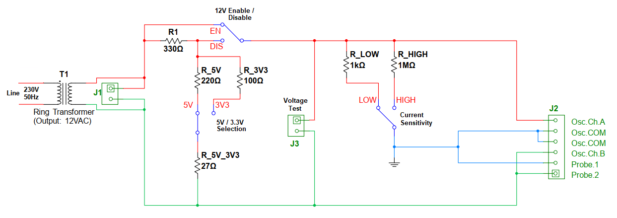
But I slightly modified the Octopus Circuit by additional switches and resistors. My bell/ring transformer's output is 12VAC and I would like to be able to perform test at 5V and 3.3 V levels as well. "12V Enable/Disable" Switch, R1, R_5V_3V3, "5V/3.3V Selection" Switch, R_5V and R_3V3 provide that ability.
R_LOW, R_HIGH and "Current Sensitivity" Switch provides better sensitivity to test lower capacitors etc., the components create higher impedance under source frequency.
J1 is the main power (12 VAC) connection point.
J2 is the interface. "Osc...." pins are oscilloscope connections and "Probe.x" pins are where the component to be connected for testing (or you may prefer to connect test leads, of course).
J3 header is just to verify operating voltage, it's an optional part.
I would like to give some notes:
a. Depending on component and test voltage, you are going to need adjusting vertical scale of Ch.A and/or Ch.B. You can also play with horizontal (time) scale, it will not effect size of shape but shall make the trace steady or flowing/blinking.
b. If test subject creates high impedance under AC (for example a low-valued capacitor), you have to switch current sensitivity to HIGH. By the way, if you perform test at lower voltage levels (3.3V or 5V), noises would be visible on trace. To reduce visibility of noises, try 12V level but you have to be sure that it will not damage the subject under test (or the other components of board contain test subject).
c. If you try to test zeners under their breakdown voltage, they react as ordinary diodes only. So my circuit simply able to test zeners < 12V but not higher.
Finally please note that you may need to adjust resistors depending on output voltage of your transformer.
Finally, let you test yourself by oscilloscope screenshots. What are those components? Enjoy!
Tipp: The "L" form is a diode :)
Additional: 50-60 Hz sinusoidal signal is enough to test almost all kind of components. However, if you would like to test especially inductors or very small capacitors (picofarad or less), higher frequencies should be used.
Edit:
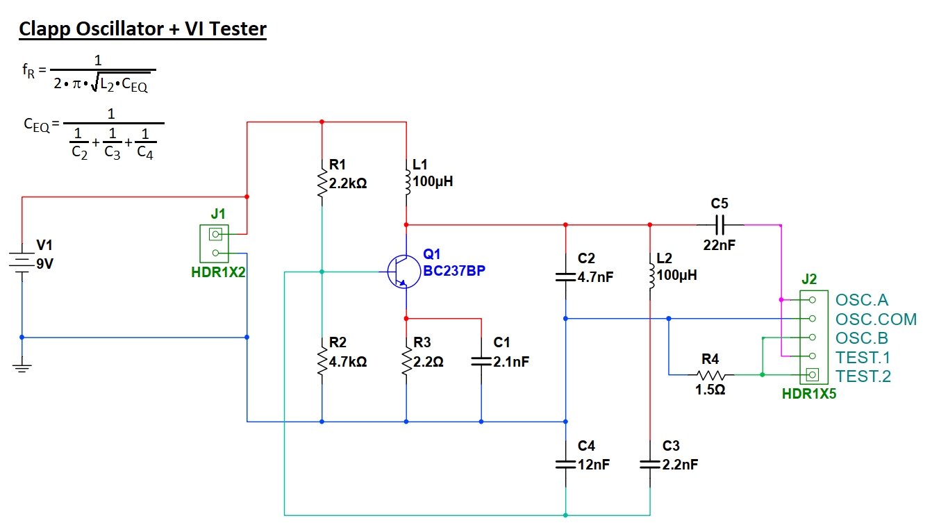
An alternative V-I Component tester is as follows. It's based on a 436 kHz oscillator theroretically, but I achieved 500 kHz on practice (yes, very small variations on parameters -capacitors and inductors- makes significant effect). By combining oscillator output with a 22nF capacitor (C5, for DC suppression) and a 1.5 ohm resistor (R4, for current sensing), it became suitable only to test inductors at very low ratings (down to few microhenries).
However on such high frequencies you have to note that you may see;
- open circuits or semiconductor junctions (P-N) as "capacitors", or,
- short circuits or resistors as "inductors"
depending on oscilloscope settings you use.
It's because on such high frequencies, components' inductive- or capacitive characteristics became more visible. Besides; inductive- and capacitive-characteristics of each- and between- PCB routings and components becomes significantly effective.
As an example, I also made a 10 MHz and a 48 MHz prototypes, but they read open circuits as a pF-level capacitor, and a short circuits as a pF-level capacitor + resistor couple; as well as both of them read inductors as resistors only.


Comments
Please log in or sign up to comment.