In Japan, Aged parents who live in the countryside increase. A family of children who lives far away always worries about their parents living in the countryside. Children cannot telephone their parents every day. On the other hand, their parents also tend to feel resistance to the daily phone of children. Because of Children's school and work, it is also difficult for the family of children to live near their parents.
2. How I am Trying to Solve It?This System comprises Monitoring Terminal and AWS (Amazon Web Services). The Monitoring Terminal includes AVR-IoT WA module connected sensors to monitor the parents' room environment and the parents' safety confirmation, and will help send the data through a fast and secure path to AWS. The AWS has AWS IoT Core connected to the AVR-IoT WA module, and has AWS CloudWatch to store the data as the log, and then visualizes the data at the request from a family of children using AWS CloudWatch.
The AVR-IoT WA module of the Monitoring Terminal connects sensors from the ESP8266 module through the Arduino Nano module. The sensors include a temperature sensor, such as the BME280 connected to the ESP8266 module, and a light sensor present onboard. The sensors also include vital signs sensors that are connected to the ESP8266 module and monitor the heart rate of parents, such as the MAX30100 Pulse/Oxygen Sensor. AVR-IoT WA module also obtains information on the heart rate of parents from the ESP8266 module through Arduino Nano module every press ENTER button. The ENTER button present onboard is used for parents' safety confirmation. AVR-IoT WA module sends information on the heart rate of parents to the AWS IoT Core through a fast and encrypted path as the parents' room environment information. Data from the sensor display using the ESP8266 module on an OLED display, such as theSSD1306 so you can locally view and confirm the data, and OLED also reduces space and power.
Here is that the Monitoring Terminal Circuit Diagram made with KiCad. The SSD1306, the BME280, and the Max30100 are connected ESP8266 module using the I2C interface. The ESP8266 module is connected AVR-IoT WA module through the Arduino Nano module using the I2C / SPI interface. The Arduino Nano module works as a Slave Mode of I2C / SPI.
The Monitoring Terminal consists of Access Board and Sensors Board. The Access Board includes the ESP8266 module, and Sensors Board contains the AVR-IoT WA module and the Arduino Nano module.
(1) Access Board
The Access Board includes the components as follows.
(2) Sensors Board
The Sensors Board includes the components as follows.
3.3 App Source Code
This system has three apps, the Access app on the AVR-IoT WA module, the Trans app on the Arduino Nano module, and the Sensor app on the ESP8266 module. Those source codes show in ’https://github.com/tomosoft-jp/monitoringsystem.‘
(1) Access app
The function ‘sendToCloud’ obtains the sensor data from the Trans app and sends those data to AWS IoT Core using Json format. The function ‘i2c_readNBytes’ receives the sensor data from the Trans app using the SPI interface. The received data are converted to Json format using the function ‘sprintf’ and saved in the variable ’json.’
“application_manager.c”
static void sendToCloud(void)
{
static char json[PAYLOAD_SIZE];
…
uint8_t sw0 = SW0_GetValue() != 0; // tomosoft
uint8_t buf[4] = {0xf2,1,2,80};
…
// This part runs every CFG_SEND_INTERVAL seconds
if (shared_networking_params.haveAPConnection)
{
…
i2c_readNBytes(0x21, &buf[0], 4);
//len = sprintf(json,"{\"Lightx\":%d,\"Temp\":%d.%02d}", light,rawTemperature/100,abs(rawTemperature)%100);
Len=sprintf(json,"{\"Light\":%d,\"Switch\":%u, \" Temp\": %d.%d,\"Hart\":%d,\"Spo2\":%d}", light, sw0,buf[3]/8,buf[3]%8,buf[1],buf[2]);
debug_printInfo("json: %s",json);
}
if (len >0)
{
…
(2) Trans app
The Trans app works in Slave mode of the SPI interface and the I2C interface, and has the event process ‘requestEvent’ for the I2C interface and interrupt process ‘ISR’ for the SPI interface.
“datatrans.ino”
//----------I2C requestEvent---------
void requestEvent() {
Wire.write(sendbuf[0]);
Wire.write(sendbuf[1]);
Wire.write(sendbuf[2]);
Wire.write(sendbuf[3]);
}
//----------SPI Interrupt---------
ISR(SPI_STC_vect) {
rxdata = SPDR;
intrpt= 1;
if (rxdata == rcvbuf[0]){
if(spipint == 5)
{
if(rcvbuf[4] == (uint8_t)((rcvbuf[0]+rcvbuf[1]+rcvbuf[2]+rcvbuf[3]) & 0x7f))
{
for (int i=1; i <= 3; i++)
{
sendbuf[i] = rcvbuf[i];
}
}
}
spipint = 1;
}
else{
if (spipint >= 5)
{
spipint = 1;
}
else
{
rcvbuf[spipint] = rxdata;
spipint++;
}
}
}
(3) Sensor app
Function ‘displaydata’ reads the sensor data from the BME280 and the Max30100, and displays the sensor data on the SSD1306, and then sends those data to the Trans app. Function ‘readData’ reads the Temperature from the BME280. From the Max30100, function ‘pox.getHeartRate’ reads the Heart rate, function ‘pox.getSpO2’ reads the SpO2. Those data are displayed on SSD1306 using the function ‘display.drawString.’ After that, those data are transferred to the Trans app 1 byte at a time using the function ‘SPI.transfer.’
“vitalsensor03.ino”
void displaydata()
{
…
readData();
temp_cal = calibration_T(temp_raw);
…
heart = pox.getHeartRate();
sp02 = pox.getSpO2();
Object = temp_act;
…
// clear the display
display.clear();
// draw the current demo method
// Font Demo1
// create more fonts at http://oleddisplay.squix.ch/
display.setTextAlignment(TEXT_ALIGN_LEFT);
display.setFont(ArialMT_Plain_24);
display.drawString(0, 0, "Hart:");
String(heart).toCharArray(charBuf, 16) ;
display.drawString(75, 0, charBuf);
display.drawString(0, 19, "Spo2:");
String(sp02).toCharArray(charBuf, 16) ;
display.drawString(75, 19, charBuf);
display.drawString(0, 38, "Temp:");
String(Object,1).toCharArray(charBuf, 16) ;
display.drawString(75, 38, charBuf);
// write the buffer to the display
display.display();
sendbuf[1] = (uint8_t)heart;
sendbuf[2] = (uint8_t)sp02;
sendbuf[3] = (uint8_t)(Object*8);
sendbuf[4] = (uint8_t)((sendbuf[0]+sendbuf[1]+sendbuf[2]+sendbuf[3]) & 0x7f);
for (int i=0; i <= 4; i++){
digitalWrite(SS, LOW);
SPI.transfer(sendbuf[i]);
digitalWrite(SS, HIGH);
delay(10);
}
}Heart rate, SpO2, and Temperature are displayed on the SSD1306 as follows.
This system uses AWS IoT Core and AWS CloudWatch. The IoT Core receives sensor data from Monitoring Terminal and collects them, then output the sensor data to the AWS CloudWatch. The CloudWatch saves them as log data. In response to the family of children request via the internet, the CloudWatch visualizes data obtained from the log data in a graph and table. The family of children can confirm the parents' condition on the visualized data.
The AVR-IoT WA module securely is connected to the AWS IoT Core by the following method. After connected, the AVR-IoT WA module sends data to the AWS IoT Core.
・Configure the AWS IAM with appropriate permissions
・Use the IoT Provisioning Tool to authenticate the AVR-IoT WA module with the AWS IoT Core
(1) Configuring AWS Identity and Access Management (IAM)
Open the IAM module in AWS and select “Policies” in the menu on the left-hand side. Click “Create policy” and select the “JSON tab.” Copy and paste the contents of “MCHPProvToolAccess.json” and name it “MCHPProvToolAccess” before clicking “Create policy.” Click “Users” followed by Add user. Give it a user name ”provtooluser” and click “Create group “and name it user group name “provtoolgroup” as follows.
Proceed to click “Next” until the following review screen. Review the details and click “Create User”. A set of user credentials generates. Make a note of the ‘Access key ID’ and ‘Secret access key.’
(2) Provisioning of the AVR-IoT WA module
Open the Command Prompt for Windows® and navigate to the IoT Provisioning Tool folder. Run “aws configure” and enter the fields being asked for. The access credentials are the ones from the IAM section.
$ aws configure
AWS Access Key ID [None]: AKIAWDV5V***********
AWS Secret Access Key [None]: *********************
Default region name [None]: ap-northeast-1
Default output format [None]:
Connect the AVR-IoT WA module through USB to the Windows® PC. With the AVR-IoT WA module connected and the AWS credentials set, the provisioning tool can create and upload the certificates.
$ iotprovision-bin.exe -c aws -m mar --force
......
......
......
Rebooting debugger
Done.The sensor data received the AWS IoT Core transfers to the AWS CloudWatch by the following method.
・Configure rule using the query statement
・Display setting on the CloudWatch
(1) Configure rule using the query statement
Open the IoT Core module in AWS and select “ACT”, then “ルール” in the menu on the left-hand side. Click “作成” and set the rule name “health” and the rule query statement” SELECT * FROM ‘(Thing)/sensors’.” Click “アクションの追加” and select “CloudWatch Logsにメッセージデータを送信する.” Set the log group name “healthgroup” and the role name “healthrole,” and then click “ルールの作成.” The rule generates as follows.
(2) Display setting on the CloudWatch
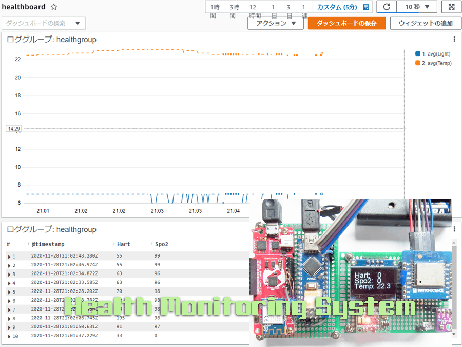
Open the CloudWatch module in AWS and click “ダッシュボード” in the menu on the left-hand side. Click “ダッシュボードの作成” and set the dashboard name “healthboard.” Click “ウィジェットの追加” on the upper right and generate 2 widgets as follows.
・Widget type:Line、
Query:stats avg(Light), avg(Temp) by bin(1s)
・Widget type:Log Table、
Query:fields @timestamp,Hart,Spo2 | filter (Switch = 0)
The displayed dashboard is the following.
The Monitoring Terminal, including connecting between the Access Board and the Sensors Board shows in the following image.
The data from the Monitoring Terminal to the IoT Core can be viewed by going to Test in IoT Core. The data streams out to the console, as seen in the figure below.
When the family of children accesses the dashboard from the browser through the Internet, the AWS CloudWatch displays the sensor data formatted in a graph and table on the browser as follows.


Comments
Please log in or sign up to comment.