


Hardware components | ||||||
 |
| × | 1 | |||
| × | 1 | ||||
| × | 1 | ||||
 |
| × | 1 | |||
 |
| × | 2 | |||
 |
| × | 2 | |||
| × | 1 | ||||
| × | 1 | ||||
| × | 1 | ||||
 |
| × | 1 | |||
Software apps and online services | ||||||
| ||||||
Hand tools and fabrication machines | ||||||
 |
| |||||
This project started as a simple "GPS tracker idea" and it turned out to be a “multipurpose GPS tracker”. As my first project, the learning curve has been steep, and hence I'm always open for input, feedback and improvements on the design! :)
The tracker is meant to be placed in my car and has the following features:
- Track GPS coordinates and post last known location to thinger.io IoT cloud dashboard every 2 minutes (displayed on a map). Posting to thinger.io with HTTP POST requests.
- Replies to SMS commands and return a Google map link to current or last known location (last known location if no current location is available).
- Send an SMS notification every XX kilometer (the idea is to have the tracker remind me to empty my oil catch tank every 4000km). This works as an customizable software "odometer".
During this project I quickly realized how "limited" the Arduino is in terms of available memory and I had to learn techniques to reduce overhead and make efficient code (at least I have tried to). I have also used lightweight libraries to fit everything on the chip and available RAM.
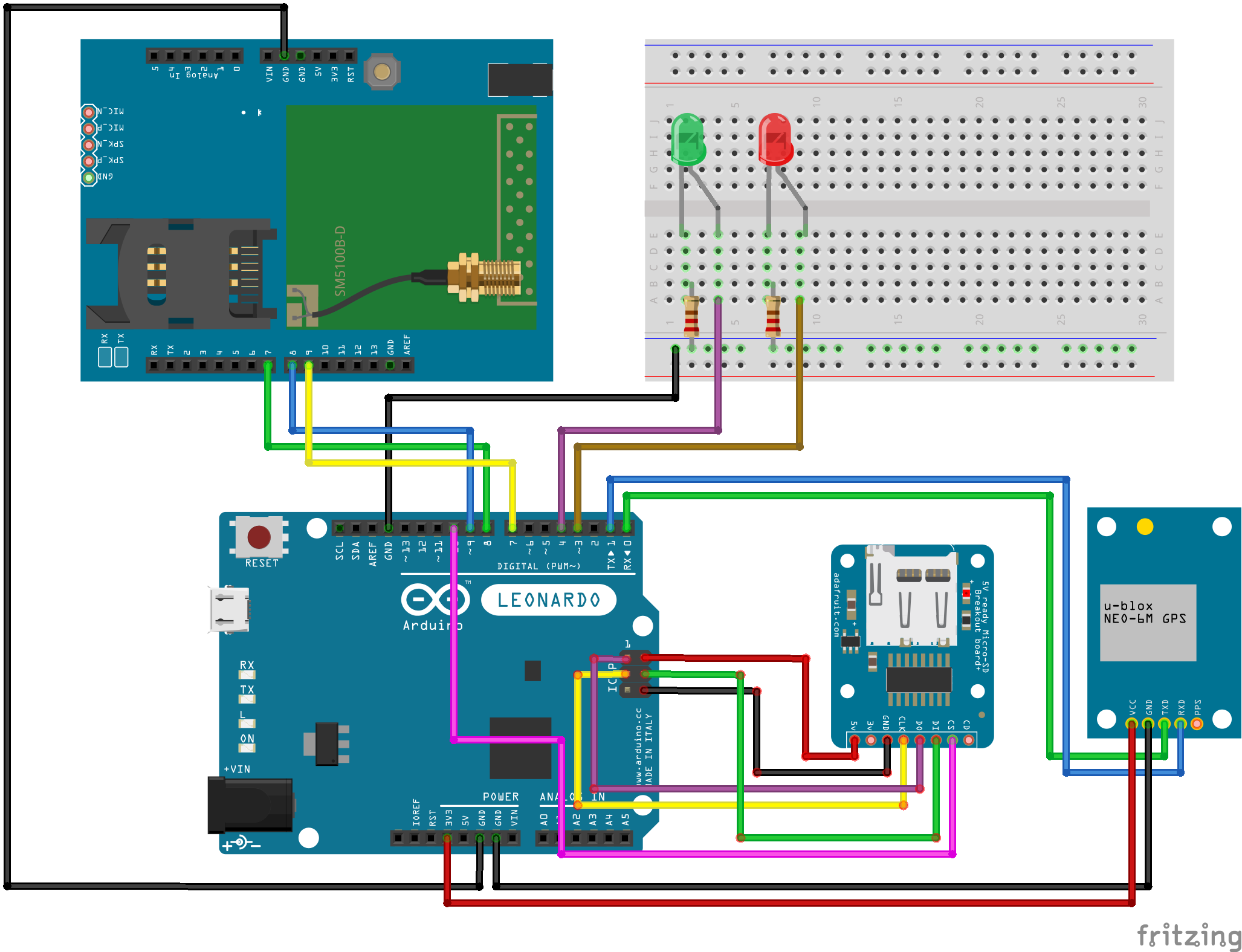
The components used are as follows (as in the component list):
- NEO-6M GPS device. This seems to be a very popular GPS device available cheap at Ebay and similar. Communication with GPS will be hardware serial.
- GPS antenna. Any compatible will do, however, I found that the cheapest ones of Ebay did not work that well, i.e. bad reception / low satellite count. Maybe I was just unlucky with the first antenna, but I had to get another better quality one for stable reception.
- SIM900 development board for GSM- and GPRS connectivity. This project should also work with SIM800- and compatible modules, no guarantees however. Communication with SIM900 will be software serial.
- Arduino Leonardo board. I have used the Leonardo board to have a dedicated hardware serial line, as we need two serial lines. While its possible to use a regular UNO board as well, you have to disconnect the GPS to download the software and also you will not have serial monitor for debugging. We need two serial lines (one for GPS and one for the SIM900 board); one software serial and one hardware serial.
- SD card reader (I have used the Adafruit card reader which is 5V compatible (made connection to the 5V SPI header easy). Other cheaper modules might work just as well. Micro SD card will be used to store distance traveled. Warning: make sure that your SD card reader supports 5V supply if following my schematics, many SD card readers only use 3.3V. Using incorrect voltage levels will most likely damage the electronics. Communication with SD card reader will be SPI interface.
- LED's and resistors to make status indicator circuits (power and GPS lock LED).
- SIM card with data.
- I have also designed an 3D printable enclosure with attached STL files that can be printed directly on a 3D printer.
First we need to install the necessary libraries. I have used the following libraries for this project:
- NeoGPS for GPS tracking and decoding. Can be installed directly from the library manager in Arduino IDE. More info: https://github.com/SlashDevin/NeoGPS
- Time library (used for UTC time zone conversion): https://github.com/PaulStoffregen/Time
Why not use the available library for Arduino by thinger.io?
Although the library provided by thinger.io Is very easy to use and would simplify things significantly, not to say already integrated in the IDE, it consumes almost 80% of storage on the Arduino Leo, leaving little to no space for the remaining code. So it is just too big for this project and we will have to do it the hard way. For communicating with thinger.io cloud we will use HTTP POST requests.
SMS commands
The available commands on SMS is as follows (all capital letters). These are the supported commands in the provided code; you can add / remove commands for your own project / requirements:
- "POS" returns the coordinates with Google Maps link, if coordinates are available. Otherwise, last known location is returned.
- "GETKM" returns the current distance since last "reset".
- "RESETKM" sets the distance counter to 0 (reset odometer).
We use the NeoGPS library for performance and resources usage over alternatives like TinyGPS++. It consumes very little RAM, and this is needed; otherwise we will get warnings for low memory and stability.
After the library is installed, modify the file GPSPort.h in the library installation path (example given is for OS X - for Windows you will find the library at a different location)
Replace all content in GPSPort.h with the following:
#ifndef GPSport_h
#define GPSport_h
#define gpsPort Serial1
#define GPS_PORT_NAME "Serial1"
#define DEBUG_PORT Serial
#endif
This file contains definitions used by the NeoGPS library. If you are using a different Arduino board, this is where you define the serial line to the GPS receiver, e.g. "Serial2", "Serial3" for Arduino MEGA.
Notes on accuracy
It should be noted that GPS is not the most accurate way of measuring and accumulating distance, as the position will drift slightly even when stationary. You can test this by standing still at the same spot and observe that the GPS coordinates will be different for every reading. For this application accuracy is less important and hence smaller deviations are OK.
I have however tried to account for small drifts in coordinates and the software only adds distance for movements over 10m (all movements below 10m is assumed stationary) over 15 seconds.
Also keep in mind that the distance is calculated in a straight line, whereas the actual distance the car travels depends on the road, bends, etc. I've set the sampling rate to 15 seconds, you can however lower this if you want higher accuracy.
Setting up PetitFSThis library is a super-lightweight library for read/write to SD cards with FAT format. It took me some time to figure out how this works, as the documentation is pretty much non-existing and some places even wrong / outdated. The provided library example code won't even compile. It comes with a lot of restrictions (as opposed to a "normal" library like Arduino's SD library or SDFat):
- Cannot create file. Only existing file can be written to.
- Cannot expand file size.
- Cannot update time stamp of the file.
- Cannot append data to file (rewrites file every time).
- Only one file open at any time.
Why use a small and limited library with lots of quirks?
Size, basically. I have tried a few libraries including the Arduino SD Library, SDFat and also fat16lib. They are all too big to make all the code fit on the chip, so to not remove functionality I used this library (the standard Arduino SD library takes approximately 12% more space). Even with all the quirks and limitations, it still provides what we need for this application: simple read- and write of a single value for storage.
If you don't use all the code and there is enough space to squeeze in some extra, it's a lot easier to work with libraries like the standard SD library.
Open the file pffArduino.h from the PetitFS library folder. Change the SD_CS_PIN to 10. This is the SS pin used for communicating with the SD card with SPI.
Open the file pffconf.h from the library folder. Disable the following options by switching the set value from 1 to 0:
- _USE_DIR
- _USE_LSEEK
- _FS_FAT12
- _FS_FAT16
By disabling these options the compiled program takes up less space - which is needed; The final sketch takes approx. 96% of storage.
On first import of the library you will get a compilation error that *can* be ignored (second compilation the error do not show - still don't understand why). However, if you want to fix this (it will re-appear every time you start Arduino IDE -> compile) add the missing function return parameter "FRESULT" as shown in the screenshot above. This is in the file pff.cpp in the library folder.
I have tried my best to figure out how this library works and although I've got everything to work, I'm pretty sure things can be improved too. If you find mistakes or improvements in the routines I have written, please feel free to share! I'd very much like to learn and build more experience.
Prepare the SD card
I have used a Micro SD card for this project. Since the library cannot create the file(s) itself its important to create the file "dist.txt" and "settings.txt" on the card before use. I recommend copying the attached "dist.txt"and "settings.txt" file from this project page, as these files already has the correct format and works (the library is very picky on text format and content).
Before you put the file onto the Micro SD card be sure to format the card properly (as FAT32). I recommend using the official "SD Card Formatter" from SD Association: https://www.sdcard.org/downloads/formatter/.
Making sure the SD card works (read / writes to file correctly)
The PetitFS library is very picky on the input files. If you boot the device and no output is shown in the serial monitor (just blank) it is most likely stuck in the "loop" where it tries to read the file from card but cannot for some reason (initializeSD() function). I've had countless of text files where it for some reason has been unable to read, hence I have included the referenced text files I have used that works. Place these reference files on the SD card and it should be able to both read and write correctly to it.
Another option can be to populate the text file with a number that is larger than the one its writing. I have not tested this, but since the library cannot expand the file size itself, I'm assuming this could be a problem.
PetitFS will write the entire length of the character array to file, hence you will see empty spaces in front of the actual number (unless the number is big enough to fill the array - the "array" length is defined in the code). These spaces must be kept when making changes to the file - as PetitFS cannot make file size changes, it can cause problems if the number of characters are changed.
Set the "dist.txt" file to "0" if you want to odometer to start at "0", or any other number to make it easy to verify that it works, e.g. sending "GETKM" command to verify SMS reply.
In "settings.txt" you set the notification trigger distance, the distance where the odometer triggers the notification SMS (in meters).
Prepare the SIM900 boardA few things must be set up on the SIM900 board before we can use it. For details there is a great resource over at https://lastminuteengineers.com/sim900-gsm-shield-arduino-tutorial/ for the setup of this board.
Power source
The Arduino board is not capable of supplying enough power, hence we must use an external power supply. As spikes can draw up to 2A make sure to use a power supply that can deliver at least 2A at 5V-9V DC; it uses the barrel 5.5mm connector.
Power source selector
Next to the DC jack is a power source selector. To use external power source, move the slider as shown in the picture above.
Serial selector
Set the board to use Software Serial by aligning the jumpers as shown above.
Software trigger
Instead of manually pressing the power key every time, you can turn the SIM900 on/off in the software. To do so the jumper named R13 must be soldered. The board is then powered up by connecting the SIM900 pin #9 to Arduino pin #7 (as shown in the schematics).
If keeping the "manual power on" functionality, the "SIM900power()" function in the code can be removed.
RemoveSIM card PIN lock
Be sure to remove the PIN lock on the SIM card before use. This can be done by inserting it into any regular phone and remove the pin lock from the applicable settings menu.
Also note that the SIM900 module in the schematics might look different than the actual board, however, the pin layout is correct which is the most important part.
SIM900 firmware version (Important!)
It is very important to have the correct version of the firmware loaded on the chip. This is because one of the commands to correctly set up the HTTP POST header is not supported until version B10 of the firmware. This means that you need to have at least version B10 or higher for the http communication to work. Specifically, with a lower firmware version it will not be able to set "Content-type" in the http header. If the content-type is not set to "application/json" in the post request, it will be rejected by the server.
To check your firmware version use the following AT command:
AT+CGMR
The SIM900 chip will then give you the current firmware version in the output console. Put the following at the end of the setup() section to print the firmware version at startup:
SIM900.println( F("AT+CGMR") );
In my case it would show this (before I updated):
Revision:1137B01SIM900M64_ST_AM
This was the oldest possible firmware version for this chip ("B01"), so I updated to version B10: 1137B10SIM900M64_ST. Newer firmwares should also work.
I will not cover how to update the firmware in this guide, there is already an excellent guide how to do this: SIM900 firmware update - ACOPTEX (although a somewhat painful process).
I don't know if this will be the case for other chips like the SIM800, however, this being a newer chip I'd say its more likely that this is already in place there.
Code adjustmentsTo adapt the code for your own project a few adjustments are needed:
- Change APN (network provider) information.
- Modify the thinger.io URL to match your own (the URL links the update request to your own "bucket" with access token). This is covered in the "thinger.io integration" chapter.
- Set correct time zone.
- Set trigger distance for SMS notification
- Set (or disable) SMS notification text.
- Set default phone number for notification.
APN provider
void connectGPRS(){
...
 SIM900.println( F("AT+SAPBR=3,1,\"APN\",\"TeleXXX\"") );
 delay(1000);
 updateSIM900();
...
Under the connectGPRS() function you will find the APN name given by your network provider, shown above as "TeleXXX". Replace this with your own APN name.
AT
OK
AT+CMGF=1
OK
AT+CNMI=1,2,0,0,0
OK
AT+SAPBR=3,1,"CONTYPE","GPRS"
OK
AT+SAPBR=3,1,"APN","TeleXXX"
OK
AT+SAPBR=1,1
OK
AT+SAPBR=2,1
+SAPBR: 1,1,"36.57.240.233"
OK
Above: output of the connectGPRS() function when the connection is working. All commands should return "OK" status.
Time zone
#define UTC_OFFSET 1 // set time zone offset, i.e. 1 = UTC+1
In the "define" section, set the time zone according to your requirements. The code is set to UTC+1.
SMS notification
I have set up a notification every 4000km to empty my oil catch tank. As I realize that most people don't have an oil catch tank, this notification should then be changed to whatever you want (or disabled altogether).
void loop() {
...
 // sends notification on SMS if the total distance exceeds 4000km
 if (totalDistance > triggerDistance) {
   char sms_msg[160];
   char distanceTotalMsg[10];
   itoa( (totalDistance / 1000) , distanceTotalMsg, 10);
   sprintf(sms_msg, "Empty catchtank! Current distance: %skm", distanceTotalMsg);
   textMessage = "";
   totalDistance = 0;
   // sets the default phone number to trigger notification
   number = DEFAULT_NUMBER;
   sendSMS(sms_msg);
 }
 ...
}
Above: code section that triggers notification (inside main loop() ).
Comment out / remove this section if you don't want any triggered notifications. Alternatively change the text to something useful.
The notification is triggered once the "odometer" (accumulated distance) reaches the configured distance set in "settings.txt" file.
Default phone number
This is the phone number the triggered notification is sent to (as the notification do not have a "sender" number to reply to)
// phone number for triggered notification
#define DEFAULT_NUMBER "+4712345678"
Wait for serial connection
It's also a good idea to uncomment the following line in the code. This makes the Arduino board wait for the serial connection to become active, i.e. serial monitor for debugging. This way you do not miss any debugging messages in the start of the code before the serial line becomes active.
Remember to remove / comment the line before powering the Arduino from external power sources, as it will otherwise stop in an infinite loop until it connects to a PC.
// while (!Serial); // wait for serial port to connect - for ATmega32u4 (Leonardo)
I will not go into detail how to set up thinger.io as its pretty straight forward; you must create an account and a "bucket" to receive the data through their website, and a "device" which we will connect to. A "bucket" is the database for receiving data. The "device" is the connection point for our code where we decide what to do with the data (in our case, populate the "bucket" database).
Create a "bucket" as shown above with your own name and description.
Now, go ahead and create an "HTTP Device" as described in the official documentation: https://docs.thinger.io/quick-sart/devices/http-devices.
Use a short device name. As the device name is part of the algorithm that generates the authorisation key I found that a longer device name generates a longer authorisation key too. The problem? Authorisation key quickly got longer than the 256 character buffer used to send the string from Arduino. There are probably some better ways of fixing this, but I found the easiest approach to keep the device name short and avoid the issue.
In the device' callback > settings section make sure the "write bucket" setting points to the bucket created previously. This tells the "device" to write incoming data to our database.
In the device' callback > overview section make a note of the method URL and authorization header (long string without the keyword "Bearer").
To send data to a thinger.io we use an "authorization URL" in the HTTP POST request. You must then replace the URL and authorization key in the code with your own.
In the postDataThinger() function you will find the call (actual authorization key scrambled):
SIM900.println( F("AT+HTTPPARA=\"URL\",\"http://backend.thinger.io/v3/users/tom/devices/CT/callback/data?authorization=eyJhbGciOiJIUzI1NiIsInR5cdfkjowiuerdf.sdfsdf.wekrjciI6InRvcm1vZCJ9.AR1gWvIZB9KmtI-5Z12YXKuchPTGn58AkwBJSZQIoxQ\"") );
You then have to replace the URL and authorization key in the code with your own, generated by following the instructions in the link provided above.
http://backend.thinger.io/...
By default, the authorization URL generated will be https. The SIM900 do not support SSL (at least I have not got it to work), so make sure to change "https://" to "http://". The thinger API also supports non-SSL connections. This is very important. If you keep "https" it will not work. When everything works, the serial monitor should give a "200 - OK" reply when transmitting the http post request.
After the AT command "AT+HTTPACTION=1" (send HTTP POST request) you should receive a reply like this in the serial monitor:
+HTTPACTION: 1,200,0
If you receive a "400 - bad request" reply or similar..
+HTTPACTION: 0,400,51
..there is most likely something wrong with the URL, e.g. "https" instead of "http", bad syntax of the "authorisation key", etc. When you receive a "200 - OK" message the data should show up in the thinger bucket like shown below. You can also receive a 400 - "bad request" if you do not have the correct firmware as mentioned previously.
Above is a view of the bucket once the data arrives (scrambled for privacy reasons). The content (data columns) are set by the HTTP POST request syntax in the code, no setup at thinger.io is needed.
Below is a serial output of the HTTP POST request as it should look when everything works. +HTTPACTION:1, 200, 0 indicates that the update was successful.
AT+HTTPINIT
OK
AT+HTTPPARA="CID",1
OK
AT+HTTPPARA="URL","
OK
AT+HTTPPARA="CONTENT","application/json"
OK
AT+HTTPDATA=84,10000
DOWNLOAD
OK
AT+HTTPACTION=1
OK
+HTTPACTION:1,200,0
AT+HTTPTERM
OK
The dashboard can then easily be set up at thinger with the maps widget using the bucket as data source.
More data to thinger?
Do you want to push more data than longitude, latitude and date/time? Just add more data fields to the http request as shown below.
Format is { "field1 name" : field1, "field2 name" : field2, "field3 name" : field3 }
sprintf(httpContent, "{ \"longitude\" : %s , \"latitude\" : %s , \"date\" : \"%s %s\" }", tempstrLong, tempstrLat, date1, time1);
The above sprintf command compiles the data string sent to thinger. The syntax is *very* strict and you must add new data fields in the exact same manner. Example is given in the code (comment section). A good idea is to make a note of the serial monitor print of the command that will show the string. You then add "field4" and so on..
EnclosureI have attached a complete 3D printable enclosure. It's designed to fit the exact PCBs used for this project. M3 screws are used for mounting.
It's designed for a 7x5cm solder board for the LED "circuit" and not a breadboard. If using a breadboard, just use some glue instead. The GPS and solder board ("breadboard") is mounted in the top casing. Use small spacers for best mounting of PCBs in top casing.
I have also kept the mounting points in the top casing solid (no holes) to make for easier printing without supports. Open these with a 3mm drill bit.
It prints well on 0.2mm without supports.
Connection to car battery / power sourceThere are probably hundreds of ways of doing this, so I don't have the only answer, or best answer for that matter; how to wire it up to the car battery. It all depends on your application, but I'll quickly describe my solution.
I wanted the device to start with the car, hence not connected directly to the battery (and drawing power while the car is turned off). So I've connected it to the "cigarette socket" circuit that is already turning on/off with the car. If you want it to be online even when the car is off, you'll have to find a way to wire it to the battery. For most cars the cigarette socket turns off with the car, but you'll have to check this for your own. I will not show the exact wiring for mine as this will also be different for every car. You can also place a battery pack in between to keep the device going for hours after the car has been switched off (or stolen..).
You can of course also just use an adapter, like one of those USB phone chargers, but that defeats my purpose of hiding it (in case the car gets stolen). We also have two power sources, the Arduino board and the SIM900 module. I used a "China cheap-o matic" step-down module, that converts from 12V-5V (the actual input range was said to be 9V-20V). It's probably not good quality, but has been working ok so far :)
The step-down module transforms the 12V input to 5V output to two USB female connectors. I then connected the Arduino- and SIM900 module to each of these USB outputs to power them. There are probably other and more "professional" solutions, but this was cheap and worked well enough.
I have measured the power draw during GSM activity to around 110maH, so very little power consumption. It will probably draw more power in areas with poor GSM coverage.
If an SMS command is received at the same time as the thinger.io http request is processed (while data is being pushed to thinger) the command will not be picked up by the software. In this case, you will not receive a SMS reply. Send a new command some seconds later and it will work again. I've not made a workaround for this, as its not a big problem. If someone should make a fix for this, please feel free to share.
Also, if the Arduino is started in an area without network coverage, it won't reconnect when the network is available again, as it only connects during startup. I might modify the code at some point to fix this, but at the moment it


Comments
Please log in or sign up to comment.