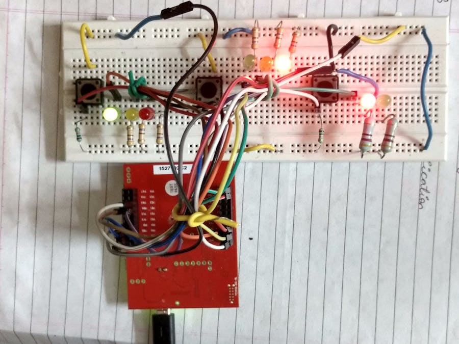
This project can be considered as getting started on TIVA C series TM4C123GXL launchpad from Texas Instruments. This launchpad has TM4C123GH6PM microcontroller and it's details are here.
I decided to make it because i want to share the basic projects and also to encourage newbees to start their own projects here on hackster.
Note: Use Code Composer Studio and Tivaware Libraries.
IntroductionThe project consists of three traffic signals: West, South and Walk. These signals are controlled by three switches (sensors in reality). The working of each LEDs are:
- Green: Go
- Yellow: Warn (turns on when there is change from green to red only)
- Red: Stop
The working is described with respect to the inputs (LSB=West Switch, Middle bit=South Switch and MSB=Walk Switch). This is as follows:
- Input 000 (Go_West): This is the Initial stage which is initialized in the code. The car will go to the west with green LED of west signal ON and Red LEDs ON for both south and walk traffic signals. (You can keep any one of the below states as initial state).
- Input 001 (Go_West): The West Switch/Sensor is active. Same output as that of initial stage.
- Input 010 (Go_South): The South Switch/Sensor is active. The Yellow LED of West traffic Signal will turn ON (Wait_West) for few seconds to warn the cars that the Red LED will be turn ON and the west bound cars have to stop. As soon as the Red LED of West traffic signal turns ON, the Green LED of South traffic signal turns ON allowing south bound cars to go. The red LED of walk traffic signal is ON.
- Input 011: The South and West Switch/Sensor are active. The Green LED of south signal will turn OFF and the Yellow LED will turn ON (Wait_South) for few seconds to warn the south bound cars. As soon as the Red LED of South signal turns ON, the Green LED of West signal turns ON. After few seconds, again yellow and then red LED of West signal turns ON and correspondingly green LED of South signal will be ON. This goes on repeating till the input is 011. The Walk signal is Red.
- Input 100 (Walk_Ped): The Walk Switch/Sensor is active. The Red LED of both West and South signals will turn ON. Green LED will be ON to allow Pedestrians to cross the intersection.
- Input 101: The Walk and West Switch/Sensor are active. In this case, Pedestrians can cross for some time and West bound cars can go for some time and the cycle is repeated. The transition from green to red is via yellow LED of West signal. In case of Walk signal, the flashing of Red LED (Red LED flashes two times) indicates that Pedestrians should hurry to be safe as the Red LED will be turn ON and Green LED of West signal will be ON. The South signal is Red.
- Input 110: The Walk and South Switch/Sensor are active. Same working as that of Input 101. Read South instead of West in above bullet point! The West signal is Red.
- Input 111: This input is an interesting case. Here all Switches/Sensors are active. Pedestrians will get some time to cross the road. West bound cars as well as South bound cars will get some time to cross the roads. Microcontroller is smart enough to avoid accident.
Take the help from the Finite State Machine attached below.
Any microcontroller can be used to built this simple project.
The video is here:The Circuit Diagram is handmade and it is correct! The project is inspired from the MOOC Embedded Systems: Shape the World.
Doubt? Comment on this project to solve it.
Any suggestion is Welcome!


_3u05Tpwasz.png?auto=compress%2Cformat&w=40&h=40&fit=fillmax&bg=fff&dpr=2)

Comments
Please log in or sign up to comment.