Project Details
This is something I've wanted to set up for a long time. The availability of these light bars makes it really simple and fun!
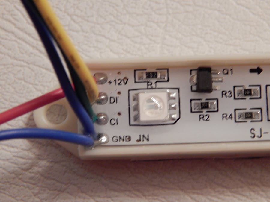
The light bar has three pin connectors at each end plus two bare wires. The input end is shown in the lead picture.
The light bar set I have has red on +12 and blue on ground, and the leads were already stripped. Connect the +12 red to the plus screw of the two terminal adapter. Connect the ground blue lead to the minus terminal screw.
The signal and power connections are clearly labeled, even if some future parts use different colored wires.
Use male to male bread board wires to connect between the Arduino and the light bar female input connector. The example code has pin 2 set up as data with a yellow wire and pin 3 as clock with a green wire. Then connect a blue wire between the Arduino ground and the light bar ground pin. That is all the wiring.
To run this, you will need the Arduino controller library from Adafruit, available from https://github.com/adafruit/Adafruit-WS2801-Library.
My sample code is available at https://github.com/dondoerres/xmaslights/
Load up the sample code, wire it up, plug in the 12V supply for the lights and the 9V supply for the Arduino, and enjoy! The show lasts about five minutes, then there is a 5 second black out, then it repeats.
Enjoy!


_ztBMuBhMHo.jpg?auto=compress%2Cformat&w=48&h=48&fit=fill&bg=ffffff)

Comments
Please log in or sign up to comment.