USB flight simulators are used with special computer software (e. g. FMS, Fig. 1) for training or skill maintenance.
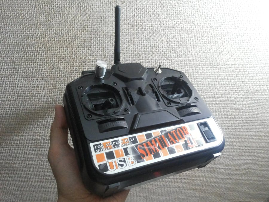
I had the simplest four-channel FS-SM020simulator with trimmers for all channels (Fig. 2).
Having disassembled it for the first time (Fig.3) I saw many holes under stickers for mounting additional controls, power socket; in addition there was a lot of empty space for all ideas described further.
All electronics had to be moved away except for potentiometers (Fig. 4).
Then I defined basic functionality of the device:
- 2.4GHz operation frequency;
- power supply from 18650 Li-Ion battery providing charging from USB-adapter without removing the battery from the transmitter;
- battery charge control;
- end point adjustments and reversal for each channel;
- simple audible indication for each operating mode of the transmitter.
After that I collected all the necessary hardware:
- ARDUINO Pro Mini board – «brain» of the transmitter, with small-sized (I had already had it in use);
- solderless breadboard – as I planned to experiment and add functionality step by step I decided not to use soldering near ARDUINO board;
- nRF24L01 module with external antenna for data transmitting;
- 5V-3.3V adapter for nRF24L01 module since the main voltage is 5V but the module requires 3.3V;
- piezobuzzer responsible for all sounds from the transmitter;;
- encoder with a switch for channel selection and adjustment;
- wires – both usual and ones for solderless setup;
- power supply system (Fig. 5) which was the first thing to make because there was no sense to continue without it.
The transmitter is powered from Li-Ion 18650 battery put in battery holder. TP4056-based module is used to control charge/discharge of the battery.A step-up voltage stabilizer provides the needed voltage (5V) to power the transmitter. Between the TP4056-module and stabilizer I put a toggle switch to power off the transmitter.
The basic circuit of power supply system is shown on Fig. 6.
Having made a stable power source I could put and connect all components mentioned above inside simulator’s casing (Fig. 7–16).
Cable straps and His Majesty hot glue have been widely used in the assembly.
White wire that goes via 10K resistor to ARDUINO Pro Mini board for battery charge level control.
To provide antenna being plugged to or unplugged from the module I had to make the hole for USB cable bigger.
TP4056-module is placed in such a way that its LED can be seen through one of holes providing visual control of charge process (red – process goes on, green – battery is charged).
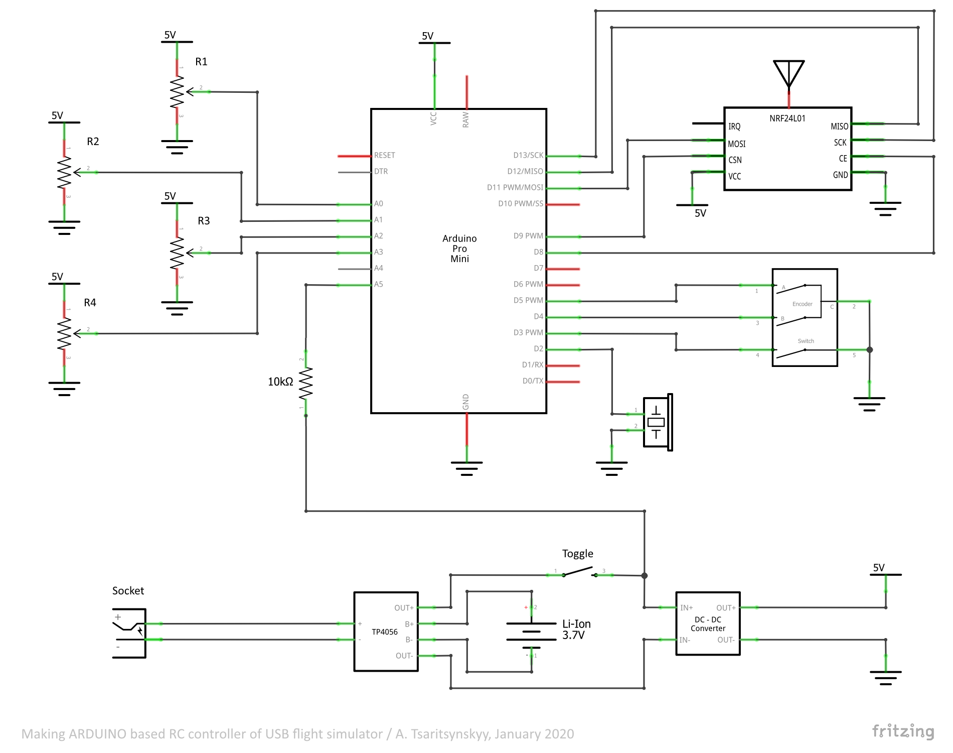
Circuit of the transmitter is shown on Fig. 17.
Free battery compartment of the simulator was used to store USB-cable and antenna when transporting (Fig. 18).
Control side is shown on Fig. 19.
To make software development easier I split the code into several files (Fig. 20):
1. VMETER.h, VMETER.cpp – contains description of VMETER class for battery charge level control. Since there is a stable power source we can estimate charge level indirectly by measuring the battery voltage. Some constants and methods are given below:
SM_FACTOR - as voltage measurements are noisy I used exponential filter. This constant defines the filter ratio from 0 to 1;
V_RF - reference voltage for measurements which matches input voltage in this case. It can be measured by a multimeter directly between VCC and GND pins on ARDUINO board when the transmitter is turned on;
V_MIN - minimal battery voltage;
V_MAX - maximal battery voltage;
VMETER(byte pin); - constructor. pin – one of analog pins which is used to get measurements;
void init(void); - should be called in setup() for the first measurement;
boolean check(void); - called in loop() for each next measurement. Returns true if voltage gets lower compared to previous measurement;
byte getPercent(void); - returns «charge percent» from 0 to 100.
2. PIEZO.h, PIEZO.cpp – contains description of PIEZO class to control piezobuzzer. Some methods are listed below:
PIEZO(byte pin); - constructor. pin – digital pin (from 2 to 7 only) to which piezobuzzer is connected;
void enable(boolean enabled); - turns on (parameter is true) or off (parameter is false) piezobuzzer;
boolean isEnabled(void); - returns true if piezobuzzer is turned on;
void shortBeeps(byte n); - plays n short beeps;
void longBeep(void); - plays one long beep.
3. ENC.h, ENC.cpp – contains description of ENC class to handleencoder with switch. Constants and methods are given below:
DEBOUNCE_DELAY - debounce timeout in milliseconds;
LONG_PRESS - long press timeout (although this function is not used in the transmitter now but I left it for further improvements);
ENC(byte pinA, byte pinB, byte pinS); - constructor. pinA, pinB – pins to which signal contacts of encoder are connected; pinS – pin to which encoder’s switch is connected;
encState getState(void); - called in loop() to get the encoder’s state (encState type is defined in ENC.h) which possible values are:
esNone– encoder has not been rotated or pressed;
esRotated– encoder has been rotated;
esPressed– short press;
esLongPressed– long press;
int getPos(void); - returns the encoder’s position. In our case:
1– rotation in one direction;
–1– rotation in other direction.
4. TR.ino – main program. In additionto VMETER.h, PIEZO.h, ENC.h standard libraries were also used:
RF24 – to work with radio module. There are no any outstanding features here so I will not consider it in detail.
EEPROM – to provide saving user’s settings into microcontroller’s memory.There is a feature here: just after the transmitter has been turned on the program checks a certain byte in memory (let’s call it the key). If its value differs from the one defined by user it means that settings have not been saved ever before and now it is time to write their default values as well as proper key. Providing healthy EEPROM (which has limited number of rewrite cycles) at next turning on the transmitter will find the key and restore user settings.
What has to be stores as “user settings”? According to requirement list above these are end points and reversals for each channel. In what way should they be stored? Here I have some math.
Let’s assume we have to control a servo on some channel and define end points of stick and servo as shown on Fig. 21.
Then the dependency between stick xin and servo xout position is
xout = aout + (xin – ain)× (bout – aout) / (bin– ain).
If we take minimal and maximal digital levels of voltage being measured on a potentiometer then ain = 0, bin = 1023, and we can simplify the formula
xout = aout + xin × (bout – aout) / 1023.
Let’s define a coefficient to adjust end points for the channel with servo
k = (mout – x’out) / (mout– xout),
where mout = 0.5 × (aout + bout) – servo’s middle position; x’out – desired servo position taking into account end points defined by user. Expressing that position from the formula above we get
x’out= 0.5 × (aout+ bout) × (1 – k) + k × xout.
Changing the sign of k we can reverse the control.
Thus microcontroller’s EEPROM will hold four coefficients according to the number of channels.
Encoder is used to adjust those coefficients. Pressing the switch selects the channel, rotating the shaft adjusts and points and reversal. When the next channel is selected the coefficient k for the previous one is being saved to EEPROM of microcontroller.
Some constants, variables and functions from TR.ino are given below:
K_MIN - Minimal value for coefficient k;
K_MAX - Maximal value for coefficient k;
K_STEP - Step for coefficient k;
EEPROM_KEY - Key for EEPROM;
EEPROM_KEY_ADDR - Address in EEPROM to store the key;
BATTERY_CRITICAL - «Charge percent». If voltage becomes less than this constant the transmitter alerts via piezobuzzer;
CHECK_INTERVAL - Timeout in milliseconds between voltage measurements.
typedef struct {
unsigned int Min;
unsigned int Max;
float k;
} ch;
ch chs[CH_COUNT] = {
{700, 2100, K_MAX},
{700, 2100, K_MAX},
{700, 2100, K_MAX},
{700, 2100, K_MAX}
};
This is an array of structures for each channel. Here you should define:
- default end points aout and bout (see Fig. 20), for servos it is suitable to use values in milliseconds;
- default value of coefficient k;
unsigned int convert(unsigned int v, int c) - implements formulas proposed above. v – digital level of voltage from potentiometer; с – index of channel from 0 to 3. Returns just the x’out.
void writeSettings(int c) - writes settings to EEPROM for channel с;
void readSettings(void) - reads settings from EEPROM for all channels.
Flashing process of ARDUINO Pro Mini board via USB-TTL adapter is shown on Fig. 22.
The power is switched on/off by the toggle. After one long beep the transmitter becomes active and the transmitter is ready to use.
To adjust the transmitter you should press the encoder’s switch. You will hear one short beep which means that you are able now to adjust the first channel(when adjusting the number of beeps corresponds to a channel index). Rotate the encoder’s shaft to adjust the end points and reversal. When it is done press switch again to move to the next channel. After all channels have been adjusted you will hear one long beep and the transmitter will return to its normal mode.
When the transmitter reaches the critical charge level it sends warning long beeps with timeout specified.
You can charge the transmitter via 2.1–5.5 socket with 5V power adapter (1A or higher recommended).
Operation checkBelow you can find a sketch for a simple receiver to check if the transmitter works properly. I used ARDUINO Nano board and another nRF24L01 module with adapter (Fig. 23).
Circuit of the receiver is shown on Fig. 24.
Having turned on the transmitter and the receiver you can watch values from each channel coming via serial port (Fig. 24).


Comments
Please log in or sign up to comment.