


Hardware components | ||||||
 |
| × | 1 | |||
| × | 1 | ||||
| × | 1 | ||||
 |
| × | 3 | |||
 |
| × | 1 | |||
 |
| × | 1 | |||
Software apps and online services | ||||||
 |
| |||||
This project was born as a result of a longing for trying this area of photography. Below you will see a simple Arduino-based setup I built to make high-speed photos of water drops.
First of all you should have a photocamera with manual settings and an external flash light, both of them must support remote control. I have Sony DSC-HX300 (Fig. 1) and GODOX SY8000 (Fig. 2) with cables.
In Fig. 2 one can see two Arduino wires carefully insulated and attached to the PC-connector of the SyncCable.
I decided to modify the remote control by adding a simple 3-pin header (Fig. 3).
Inside the remote control (Fig. 4) there are three springy metal strips (1 – «+» of the shutter; 2 – GND; 3 – «+» of the autofocus) which short out two circuits («2–3», then «1–2») when the button is being pressed.
Since the pin header is now installed we can emulate the button press programmatically using Arduino.
The SyncCable works in the same way: the contacts in the PC-connector have to be shorted out to fire the flash.
My goal was to capture the moment of splash when a drop falls onto the water surface.
To simplify the setup I used some parts of a medicine dropper assembled together (Fig. 5).
The laser module KY-008 and the LM393-based light sensor module will detect the drop falling (Fig. 6).
It is possible to arrange these modules in such a way that the falling drop will interrupt the laser beam thus breaking the circuit. The light sensor is capable of adjusting its sensitivity to the laser power by rotating the variable resistor on the module. Additionally, the modules can be positioned at a long distance from each other.
The shooting is conducted in the darkness using long exposure for several seconds so that only short-time flash light matters for the final results.
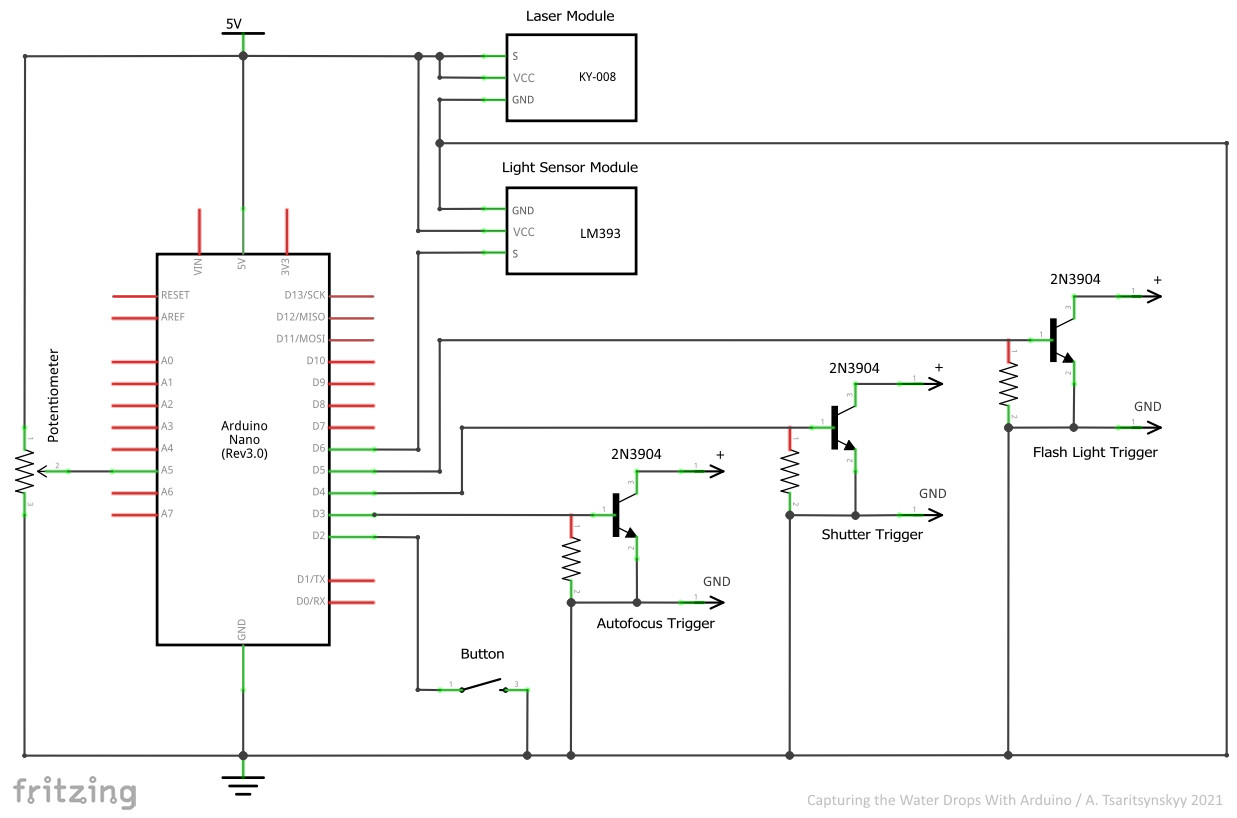
The circuit diagram is shown in Fig. 7.
The setup is not fully automated. Before the observable drop separation the user presses the Button. This opens the shutter for a few seconds through shortening out the contacts consecutively in the remote control by Autofocus Trigger and Shutter Trigger. Also the Button press allows firing the flash light. When the drop crosses the laser beam the Flash Light Trigger shorts out the contacts in the PC-connector and the flash light fires. The time between crossing the laser beam and shortening out the contacts in SyncCable is adjusted by the Potentiometer in a range from 1 to 500 ms. (limits can be changed in the code). In this way, different moments of the splash can be captured. Next drops do not fire the flash light: to activate this function the Button has to be pressed again.
The assembly is shown in Fig. 8.
An optical coupler can be added in the circuit above to separate the high-voltage flash light from low-voltage electronics.
The main code parameters are shown in Fig. 9. The project is based on Arduino Nano.
The flag «DBG_MODE» is intended for the preliminary arrangement and adjustment of both the laser module and the light sensor module. In this mode, neither the camera nor the flash light is used. The Arduino board built-in LED serves as an indicator.
To adjust the setup uncomment the flag, compile the code and flash the Arduino. If the setup is correct, the LED goes ON when the Button is pressed (shutter simulation) and goes OFF when a drop crosses the laser beam (flash light firing simulation).
When the setup works well comment the flag back, compile the code and flash the Arduino again.
The code also contains following constants:
· Arduino pins to which the components of this project are connected;
· delays applied when the contacts of autofocus, shutter or flash light are being shorted out;
· limits of the time range adjustable by the Potentiometer.
Some results are shown in Fig. 10 – 12.

Comments
Please log in or sign up to comment.