Part 1: https://www.hackster.io/tsaritsynskyyaa/mini-laser-engraver-on-28byj-48-motors-1d851f
After the events of Part 1 I wanted to make a new frame, buy a more powerful laser and move to GRBL v1.1. Operational dimensions remain the same: 80x80mm. Also I planned to use mechanics from the previous engraver.
Before doing something I made a 3D model (Fig. 1) that helped me to understand shapes and sizes of frame’s parts, position of shafts, motors, pulleys; mates between movable parts. Material of the frame: 4mm plywood. Detachable joints are made using M4 fasteners. I had not ordered a new laser module before I finished with this model so that I did not think about laser’s mounting structure. The only thing I was keeping in my mind was the fact that lasers of several watts have similar width and depth of their heat sinks: ~33x33mm.
Plywood material I have is supplied in A5 sheets (approximately) that affected the frame’s dimensions (Fig. 2). It took two sheets to cut all parts of the frame (the first one for side plates; the second one for parts between them + brackets for mechanics).
Some manufacturing moments are shown in Fig. 3–9.
Note #1 about the motor
Before attaching other structural members onto the frame it is necessary to transform our 28byj-48 unipolar steppers to bipolar ones, since using the GRBL v1.1 was stated in the task. Briefly speaking, it can be done in several steps:
1) make a hole in a plastic cover of the motor (well, in fact it can be detached with a knife or a screwdriver, but for me it was too late) to get to its PCB;
2) cut the middle track thus separating coils;
3) desolder or cut the red wire – we do not longer need it;
4) in addition, I made a new 4-wire plastic casing for the motor’s connector from the old 5-wire one, and inserted all wires in a correct order.
More info in various YouTube videos, e.g.: https://youtu.be/sY1Y_BJ-fTQ.
My result is shown in Fig. 10.
Then I attached old stuff to the new frame (Fig. 11–13).
By this moment I had already received a new laser module (Fig. 14) with a promising text on it (2.3W, 12V, TTL/PWM), fan and massive heat sink.
Note #2 about the motor
What things are changed after our motors became bipolar?
Firstly, now they are able to operate from 12V source.
Secondly, the motors demand new drivers, e.g. A4988. To use them comfortably I bought special shields (Fig. 15). It is also possible to use the CNC Shield. The driver itself has a small potentiometer responsible for adjustment of the current (more info here: https://ardufocus.com/howto/a4988-motor-current-tuning/). My little experience with 28byj-48 has revealed that all we need to do, without measurements and calculations, is to set the potentiometer in the position where the motor starts to operate reliably when you try to stop its shaft with your fingers. Lower current leads to missing some steps while higher current makes the motor heat greatly.
Thirdly, we get now 32 steps per revolution. Tests have shown that the motor misses steps in this case, but works well in a half-step mode. Fortunately, the A4988 driver allows us to set several microstep modes, and shield makes it very easy: to set the 1/2 step mode just set the switch 1 to ON.
After several tests of the assembled device my doubts got confirmed: due to the heavy heat sink and a large distance between it and X axis the laser vibrated a lot.
In the 3D model I changed the shape of side plates, so that they can still be cut out of a single A5 sheet, and moved X axis 28mm towards the center (Fig. 17).
At the same time I did not want to start from the beginning so I decided to cut side plates (Fig. 18–19) and relocate the upper axis 28mm towards the center.
There are different holes in the laser’s mounting plate: two 3mm – for radiator attachment; two threaded 3.4mm – for M4 screws connecting it to the aluminum plate of the movable part of X axis (Fig. 22).
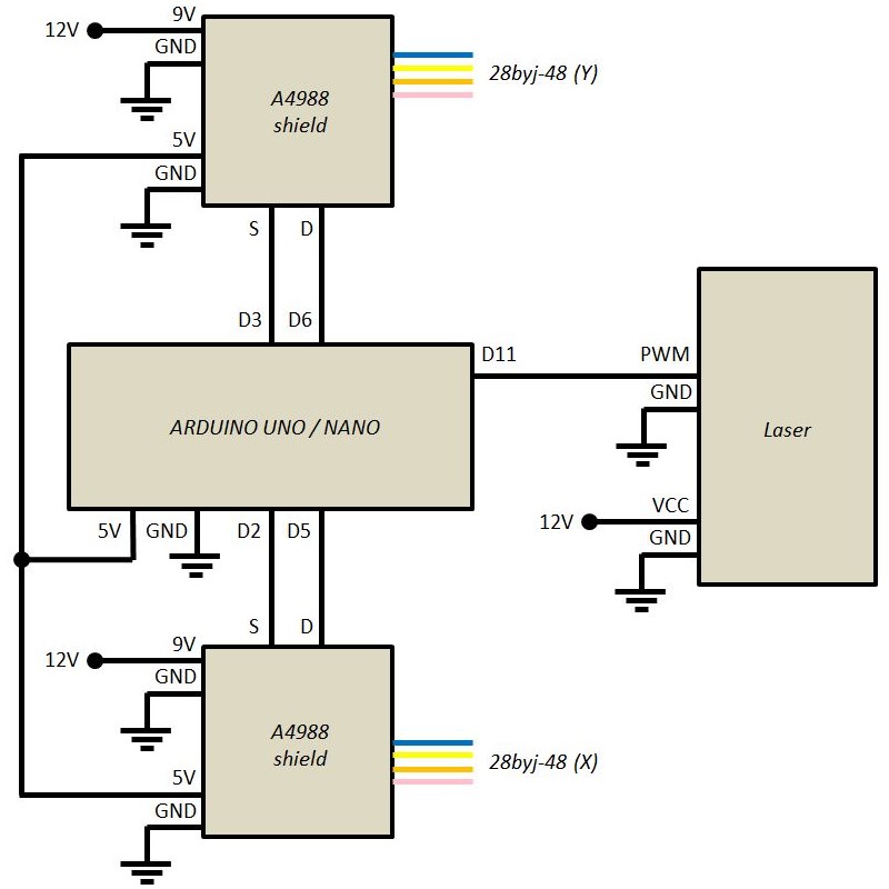
Circuit diagram is shown in Fig. 23–24.
For better understanding I recommend to get familiar with GRBL pinout, e.g. here: https://domoticx.com/wp-content/uploads/2017/05/Arduino-grbl-pin-layout.jpg.
The final photo is shown in Fig. 25.
Download GRBL v1.1 from https://github.com/gnea/grbl, flash the ARDUINO board. It is not necessary to change the sources like I did in Part 1.
The easiest way to change GRBL settings is to do it via LaserGRBL (http://lasergrbl.com/download/). Parameters changed are adduced in Table 1.
CNC is ready for further tests. For demonstration I created a combined ARDUINO + GRBL logo:


Comments
Please log in or sign up to comment.