


Hardware components | ||||||
 |
| × | 1 | |||
| × | 1 | ||||
| × | 2 | ||||
 |
| × | 1 | |||
| × | 4 | ||||
| × | 8 | ||||
 |
| × | 14 | |||
 |
| × | 1 | |||
 |
| × | 1 | |||
 |
| × | 1 | |||
| × | 4 | ||||
Software apps and online services | ||||||
| ||||||
Hand tools and fabrication machines | ||||||
 |
| |||||
 |
| |||||
This project will cover guide you to build this bot from A to Z, if it is not detail enough, then drop me a comment, I will update to project when i have free time.
Here is small video of the car :D
What you will learned after making this car:- How step motor works and how to manual send signals to step motors without library.
- How to rotate multiple step motor at same time.
- Extend arduino digital pinout to un-limit number of pins :)
- Some techniques using class and pointers in c++.
Part 1: Assemby the car bodyHere is the car body design:
https://grabcad.com/library/arduino-cleaner-bot-room-mapping-1
The car was design simple as positble, if you have a 3d printer then you can separate parts to print (this is design to print on 220x220 3d print), if you donot have one, you can manufacture it with the acrylics and the hand tools.
Assembly the wheel:
The wheel size is 40mm, you should buy some wheel with same diameter which has the rubbers, take out rubbers and assemble to this wheel or you can using that wheel with some modify to fit with the car.
Assembly the trashbox:
the trashbox distance to ground is about 5mm, i'm suggest you buy the silicon-glue to connect to the bottom trash, like this one:
Assembly cleaner rod:
just drill hole on the rod & using 502 glue, it is easier id you have a 3d printer.
Optional: the car was design to using sensor, but if you want to using the physics switch the craft addition items with the red color in the picture,
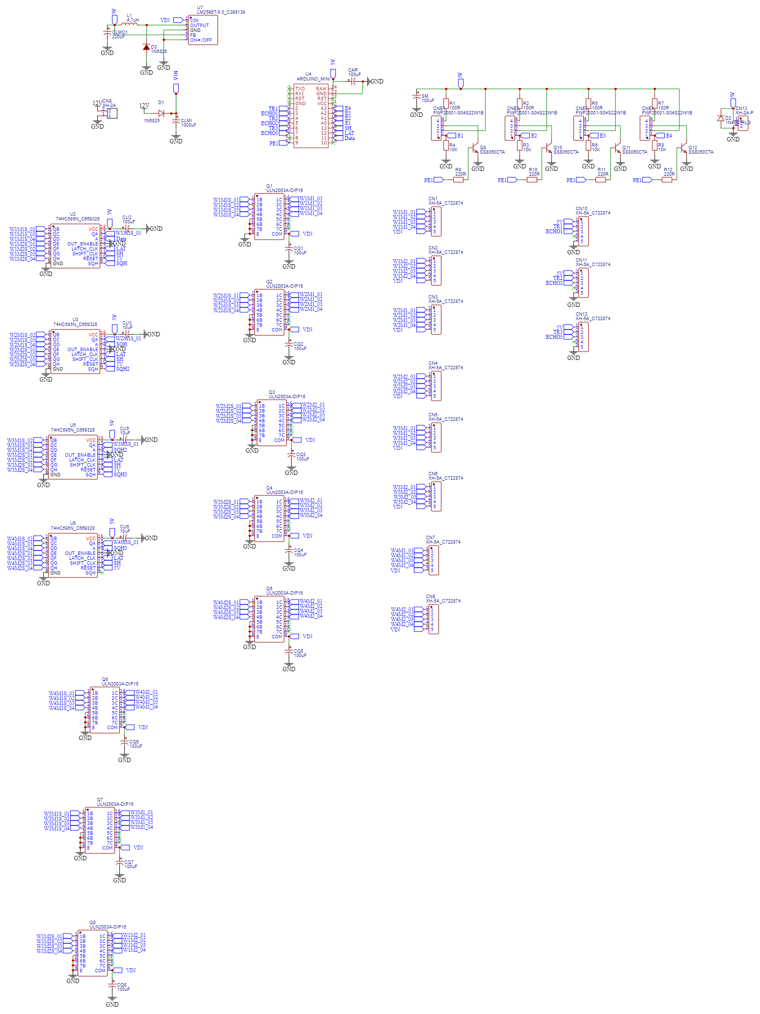
Here is the electric design: https://oshwlab.com/tungbuivn/home-cleaner-bot
PCB:
Components and explains:
How is works: The power source go though diode and to the uln2003 to provide power for the step motors, all others will go thought lm2596 to provide 5v for the rest of electric components.
Components and reason:
Why using step motor? yeah, using step motor will give you ability to control the car rotating wheel at the exactly angle you want, same the the distance, you can moving car exactly. but as you see in the short video above, it is slowly, max rpm of the 28byj-48 is 15rpm, the speed in the video is 7rpm.
Lm2596: im using this instead lm7805 because circuit will consume more ample if you connect sensor to endstop, lm7805 will fastly hot what ever it running at 500ma, but lm7805 is more stable than lm2596, using lm7805 or lm2596 depend on your decide :)
each uln2003 in the schematic has the free 3pin, so why not using it ? yeah, you may try to wiring it, but with mine, it seem uln 2003 doesn provide enough power to drive motor.
The sensor end-stop was design to using IR-LED and photo-diode, but you can using LDR with the laser ligh, or what ever you think it should work. You can search hackster to find more information about using IR-LED & photo-diode
Arduino pin connection:
D2-D7: this will connect to SRF05 sensor, this is the eyes of the car.
D9 (PE1) : send HIGH signal on this pin to provide power to sensor, send LOW to cut off
A0-A3 (E1,E2,E3,E4): signal from end-stop will be send to this pin to notify about end-stop status.
D11-D13: this pin using to control 74HC795
Header pin connection:
CN9: this is powersource 12V
CN10,CN11,CN12 using to connect SRF05 or SRF04 sensor
CNE1,CNE2,CNE3,CNE4 using to connect end-stop of the step motor
CN13 using to connect to dc 5v motor to doing cleaning job
CN1, CN2,CN3,CN4, CN5, CN6, CN7, CN8 using to connect to the step motors.
Milling the PCB:
pcb was design 2-layer but you can milling it with 1-layer and solder connecting wire to other side.
if you choosing to solder on the hole-pcb, it will abit bigger and more complex :)
Part 3: Writing code to control the carApplication Structure:
Our main car object will contains several children class include:
Driver Engine: will contain code to drive the car, driver will contain all the wheels and eyes, it will handing rotating and moving, example: if you want moving car like a real-world car then you will implement driver to control the wheel. This object also contains code to homing position of the wheels. In my source code, i have implement All-wheels driver engine, if you want control the like real-car, you need to implement other class Front-Wheel or Back-Wheel, but it is more harder, and you need some knownege about car steering to calculate rotation angle of the each wheel which using to drive car.
references:
https://en.wikipedia.org/wiki/Steering
Eye manager: the car has three eyes, so we need to control what ever the eye we want to using at the time need to decision where to go next.
A: The Cleaning botOur bot will start to clean room by the zizac line, after end of line it will find the way to moving to the left, if it cannot find the way then cleaning is completed. if it can turn left then it will set next target direction is the right and restart the loop cleaning. it's simple, right ? :D
B: The Mapping botThis is not implement yet, but here is some suggestion if you want to make one.
The first thing we know is:
At the time you turn on the car the position of it will be (x,y)=(0,0) and what ever car moving or turn left or turn right you always have the distance it moved, and the rotation angle, that mean you always have the coodinates of the car at any time, so, we have the collections of the points we call it as FreePoints
What ever car change it direction that mean we have will calculate coordinate ahead, which block car moving, so we have a second set of points, we call it as WallPoints.
From two set data above you will using delaunay algorithmic to build planar of the room from FreePoints and WallPoints, so in theory, you can move car from any point to any destination point at any time.
you will need to reference some path finding algorithmic (like NPC can moving from A to B in the game :)) to control the car if you already having map of the room.
Here is some reference code, it is small
https://github.com/mapbox/delaunator
https://mapbox.github.io/delaunator/demo.html


_3u05Tpwasz.png?auto=compress%2Cformat&w=40&h=40&fit=fillmax&bg=fff&dpr=2)
Comments
Please log in or sign up to comment.