


Hardware components | ||||||
 |
| × | 6 | |||
 |
| × | 6 | |||
| × | 3 | ||||
| × | 2 | ||||
This is upgrade from preview version of connecting the sensor Lj12a3-4z/bx to the cnc, this is more simple.
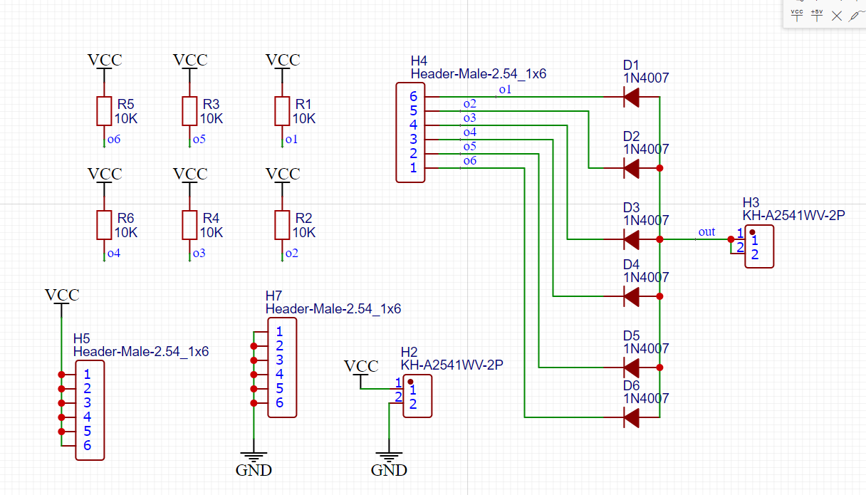
Circuit explain:
Header H2 is the power source for the circuit, six sensor VCC and GND will be connect to H5 and H7, other six pin in H4 is the output from sensor. each output will be pull-up to the VCC of power source. This is the formal NPN, the output must connect to the load, when there is no load then the heavy current will go throught the Collector of the sensor and destroy it.
Each output will be connect to the diode 1N4007 to make sure there is no voltate going to trigger pin of the cnc board, when the sensor is triggered, the GND will going to diode and to the controller board to trigger limit switch.
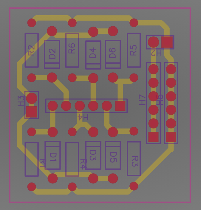
Here is the board completed.
Comments
Please log in or sign up to comment.