


Hardware components | ||||||
| × | 1 | ||||
 |
| × | 1 | |||
 |
| × | 1 | |||
When the first time I want to measure temperature with high precision, I had encounter some instruction in source code of several developer, one of them is max 31865, but when buying bread board of max31865, there are much people guide to connect the wiring, some are correct, some are wrong, so I write a tutorial to guide you to find out the correct way by yourself.
here is the picure about max31865: both of the china version and adafruit are same.
To correctly wiring this board, we need to understand how it work, and lucky, we can found very much information about it overinternet. Assume we are connect RTD PT100 sensor.
The first we need infomation about max31865 IC. As the instruction from manufacture, here is pinout from page 7
And here is wiring from manufacture from page 1
As you see, default Force2 aready short to gnd (pink and blue board above), so you have just connect all 4 wiring to board to make it functional as image bellow, althrought nothing is wrong but ussualy red wiring for (+) and green wiring used to (-), so I suggest you swap red to green position to match exactly as manufacture document.
Here is manufacture wiring guide from page 23
This is simple enough, you just need to solder A and B point as image below
The adafruit has a picture show where to solder and plug to board, I dont know why, but it is diffrent as instruction from max31865 manual on page 23
As you see, the FORCE2 pin of the board always connect to GND, so it may damage IC or work but not as manufacture expect. So to correct wiring it you need to solder point A, point B, and using paper knife to cut connection between FORCE2 and GND. Two red wire will connect to F+ and RTD+, green wire will connect to RTD- or F-.
if you are using arduino then 2 recomment not direct connect sensor to the IO pin, just because arduino only can handle 8 bit ADC resolution, you should using a something similar to Ads1115 (ADC 16 bit) (double precsision than Max31865, ADC 15 bit) or a mcu stm32 has a ADC 12 bit.
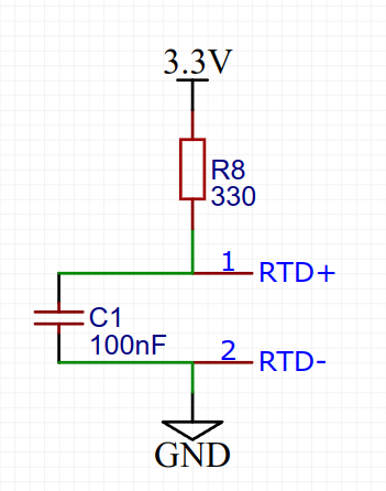
In this case everything is more simple, do you see 100nF wiring between RTD+ and RTD- ? yes, it is important to keep the value of the ADC reading from MCU smooth, if you choose manual wiring then I think you could free change value of it from 100nF to 10uF =)). Here is schematic:
how it work: with the R8 resistor then we will able get the voltage at RTD+ value, and then calculate resistor value of RTD, but the first we will need to know how to translate resistor value to temporate. Here is the formular from manufacture on page 9
this is a parabol as below, assume we are using RTD PT100
and the max value:
that mean, the max resistor value can handle is 761.25R, over this value then you may get invalid result.
finnally, we just need to convert our ADC reader from mcu pin to resistor value, we will do it as same as max31865 do.
Assume you are using GPIO directly from stm32 with resolution 12 bit (2^12=4096), if you using ADS1115 then max if when you read ADC from RTD+ then calculate resistor as following formular, as the ohm law:
MaxResolution/(330+R)=ADC/R
where:
ADC: is the value read from GPIO pin
MaxResolution:
if you use 8 bit ADC: MaxResolution=2^8=256
if you use 12 bit ADC: MaxResolution=2^12=4096
if you use 16 bit ADC: MaxResolution=2^16=65536
now when you solve R value from above formula, just subtract "wire resistor" and you get the Resistor of RTD, using formular F1 above to resolve Temperature.
if you want subtract Resistor value from wire, then using multiple meter to measure resistance of two red wire, with the RTD length 0.5meter, ussualy resistor value is 0.8R (0.5mete x2)
NOTE:I haven't doing anything above in the real-world, it is theory, you need to findout more by your self.
D. Reference:https://pdf1.alldatasheet.com/datasheet-pdf/view/492628/MAXIM/MAX31865.html
https://learn.adafruit.com/adafruit-max31865-rtd-pt100-amplifier/overview
Comments
Please log in or sign up to comment.