


Hardware components | ||||||
| × | 6 | ||||
| × | 7 | ||||
 |
| × | 15 | |||
 |
| × | 1 | |||
| × | 1 | ||||
| × | 1 | ||||
Im writing this circuit just because I had a hard time when learning electronics circuit, hope it helpful to the newbie as you and me :D
I have asked brother "google" how to do that but no lucky, so im decided to do it with my self and share wit you :D
The problems: when im craft a end-stop for my cnc, I found some online design version which doesnt using physic-switch, they called them with the name 'sensor'. When put a metal near it, it will send out a signal positive or negative depend. In this circuit, the Lj12a3-4z/bx will signal 0V when it detect a nearby metal and VCC in the rest case.
this is the fastest, you could direct diode to the output of sensor, and a pull up resistor, which will prevent VCC go throught output but let the GND pass throungt. This do work like a physics switch.
click here for the schematic & pcb
WARN: if you connect any power source to the sensor output will cause short circuit, but this method do work with the input of the mach3 bsmce controller.
solution 2:The difficult happen when the board mach3 usb only have four input port while we have six sensor, and they only accept limit end-stop on a single port(image below). Do you think we will connect all six wire output to the input port on cnc board ?
No, we cannot connect every of them just because the is one signal limit will be trigger at a time, at that time one sensor sent out 0V while others sent VCC signal, this will cause short circuit and...bump, you will buy a new board :D
Other simple solution is we can connect sensor to relay to trigger end-stop signal but the size of relay too big, and slowly, you can event ssr relay but it is exprensive and out of size too :D
Then you think about other solution is using transitors to switch signal, yeah, you are corrected, but the transitors work with 5v only :D, ofcause, there are several transitor acceptmore than 5v, but it is rarely and exprensive too.
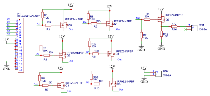
finally, you think about using mosfet, it's fast switch, cheap, and accept wide voltage range, yes, as you see the schematic bellow.
Explain schemaic:
The O1, O2, O3, O4, O5, O6 is the output from sensor, this will connect to the Gate pin of mosfet,
normaly, the sensor output is high, this will make O1..O6 open, then the R2 will trigger Q6 close, so there is VCC go throught 470R resistor.
when one of sensor sent active signal this will close trigger mosfet close, then there is VCC go thounght line to the R14, this will cause mosfet Q6 open, so only GND go throught 470R
CN2-XH2A is power source input, vcc and gnd
H1: KHA254 is 18 pin for the siz sensor
CN1: XH2A is the output, which will be connect to the input pin of the cnc board.
The 470R is the circuit protection, this will prevent short circuit when you connect to some where called "VCC" or "GND" :D
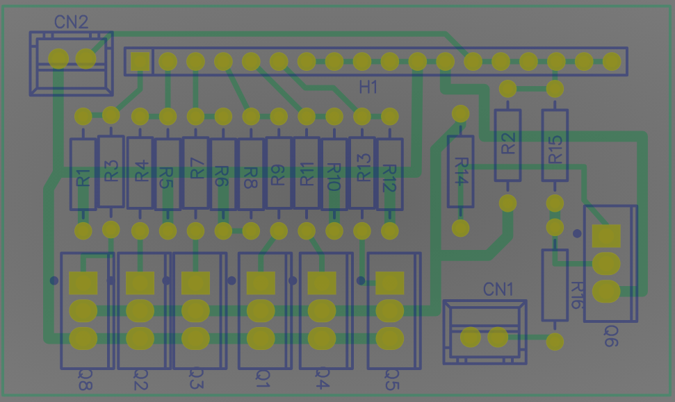
if you intend to milling this PCB by your cnc then download gerber file for using. Recomend using flatcam software and autoleveller software.
That is all, have fun DIY :D

Comments
Please log in or sign up to comment.