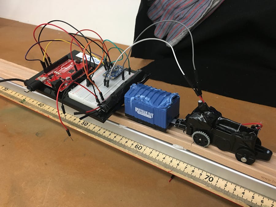
As a geophysics student at UCLA, I am interested in the small magnetic fields that are left behind when Earth's large magnetic field changes. This project is a simplistic lab model of geophysics instruments under development right now. As technology gets smaller and cheaper, it also becomes more accessible. This project showcases the versatility and customizability of using Arduino boards as data-taking devices. In short, you can reap the fun of magnetics data without hiking for miles with a heavy magnetometer backpack.
This project can be separated into two parts. The first part is taking magnetic data using the Arduino and the magnetometer. Part two is driving this magnetometer along a train track or some other linear track, all while recording magnetics data and position. The second part of the project is very cool, but very optional. I have split this project up accordingly.
Update: Fresh off the press, some data just taken using the train and an array of mounted magnets, resembling sea floor magnetic stripes.
For the Magnetometer:
- Arduino Uno
- LSM9DS1 Board
- Breadboard
- Jumper Cables
- USB to Arduino Serial Cable
- A Computer with Arduino IDE
How Does the Magnetometer Work?
The magnetometer onboard the LSM9DS1 uses a Hall Effect sensor to measure the magnetic field in three directions. Hall Effect sensors take advantage of the Lorentz force to measure the strength of magnetic fields. Lorentz force states that charges moving through magnetic fields will experience a force proportional to their charge and velocity. The sensor passes a beam of electrons, with known charge and velocity, through a magnetic field (Fig. 1-A). When the electrons are subjected to the Lorentz force, they drift off course. This creates a voltage difference in the sensor (Fig. 1-B). This voltage difference gives a measurement of the strength of the magnetic field, and the orientation of each current sheet gives its direction (Ramsden, 2006). At this time, we will be using only the measurements in the "z" direction.
Setting Up the Magnetometer
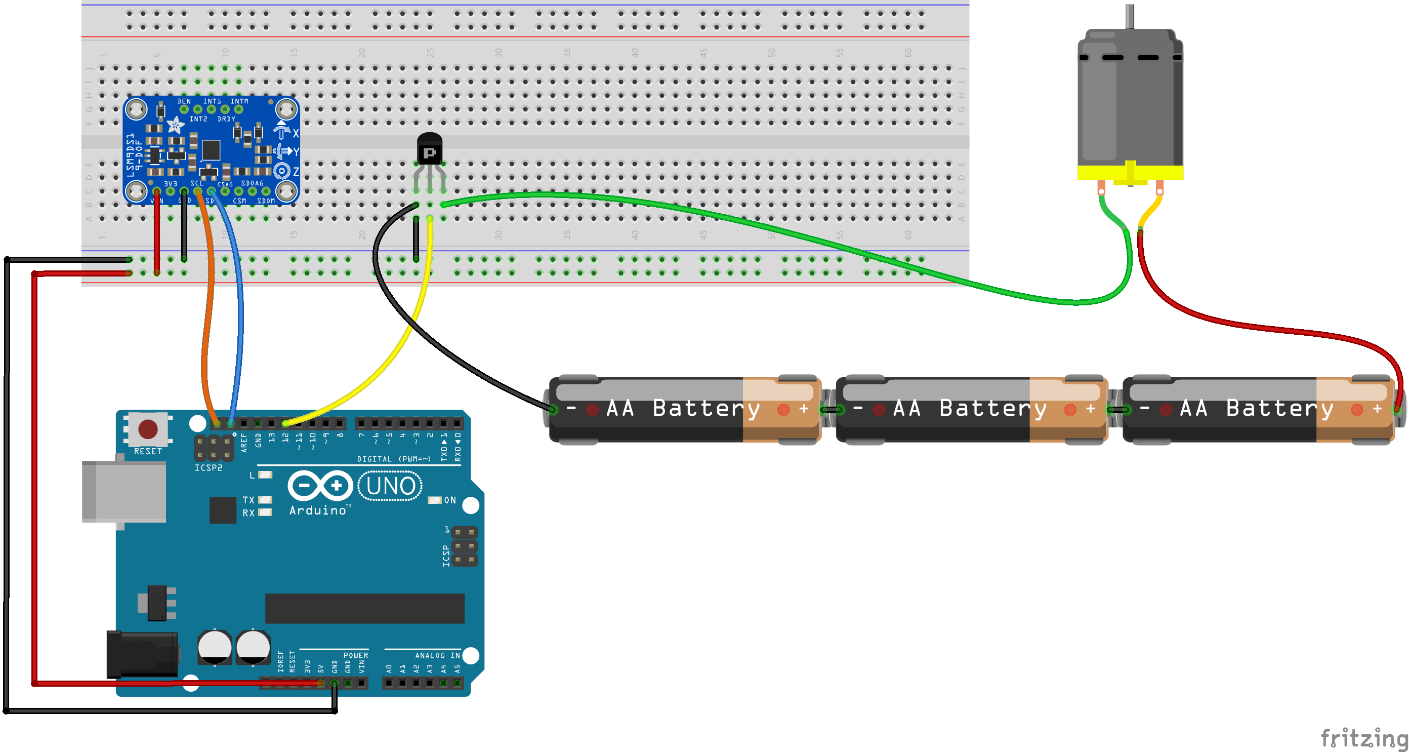
*Fritzing circuit diagram is included below*
The Adafruit breakout board can communicate with your Arduino in two different ways. We will use I2C protocol, which requires only 2 pins for communication while supporting over 1, 000 "slave" devices (provided they have their own names). SDA sends data and SCL sends clock data. SDA shows a bit of data for a certain time, and SCL communicates when to accept that data. In my mind, SCL is like a talk show host opening a prize door. The only prize options are a "1" and a "0." As the stage crew frantically scrambles to set fresh prizes behind the door, the talk show host stalls Arduino, the Italian contestant. Once the prize is set, SCL quickly opens the door, Arduino sees the prize, and SCL closes the door. Timing is everything. If SCL is too early, she will open the door before the stage crew sets the new prize- making Arduino think that he has one two unique "1's" when there was only one. If SCL is too late, she will be skipping prizes- Arduino will be robbed of his hard-earned data.
The other protocol option for our board, SPI, has a faster data transfer rate, but requires additional pins that cannot overlap ports on the Arduino. This protocol would be useful for taking magnetic data in rapid succession, but we don't need it here. This article from Sparkfun talks in depth about how I2C is well adapted to serve the demands of breakout boards for Arduino. To use the I2C protocol, we will call the library "Wire.h" at the beginning of our code (this library is included with the Arduino IDE).
The remaining two pins, ground (GND) and voltage in (VIN) are used to power the board. Ground should be connected to ground on the Arduino or breadboard, and VIN can use 3-5 V voltage supplies (both voltage outputs from the Arduino are OK). The official pinout and setup guide can be found here.
Magnetometer Pinout:
- VIN = connect to 3-5 V either on Arduino or breadboard
- GND = connect to circuit ground on Arduino or breadboard
- SDA = connect to SDA
- SCL = connect to SCL
- 3.3 = Not Used Here (3.3 V output)
- MOSI, MISO... = Not used here (SPI Pin Side)
A finished circuit diagram (below) shows the magnetometer wiring on the left and the train wiring (optional) on the right.
Adafruit Libraries:
Three libraries are used for this project.
1. Wire.h is pre-installed with the Arduino IDE to use for communication between I2C devices. The other two must be installed through GitHub.
2. Adafruit_LSM9DS1.h is the library specific to our board. This library tells the board what to measure, the range of measurement, which axes to measure on, etc. This library also uses another library (yeesh)...
3. Adafruit_Sensor.h, which is used for all Adafruit sensor boards.
Steps to Download an Arduino Library
- Step 1: Click on the links below
- Step 2: Click "Clone or Download" button
- Step 3: Click Download ZIP
- Step 4: Open Arduino
- Step 5: In "Sketch" tab, click "Include Library"
- Step 6: Click "Add.ZIP library"
- Step 7: Browse and select the libraries you downloaded
To include any library in a sketch, use the following format:
#include <Wire.h>
#include <Adafruit_LSM9DS1.h>
#include <Adafruit_Sensor.h>
Arduino Code:
Now you can run the following code (downloadable at the bottom using GitHub):
 // NoMotorMagTrain_Salty.ino
// Tristan Whisenant 7/9/2018
// Communicate with the Magnetometer while train is operated by hand (Motorized or Pulled)
///////////////////////////////////////////////////////////////////////////////////////////////////////////////////
//LIBRARIES
#include <Wire.h>
#include <SPI.h>
#include <Adafruit_LSM9DS1.h>
#include <Adafruit_Sensor.h>  // not used in this demo but required!
///////////////////////////////////////////////////////////////////////////////////////////////////////////////////
// i2c Communication Tag
Adafruit_LSM9DS1 lsm = Adafruit_LSM9DS1();
///////////////////////////////////////////////////////////////////////////////////////////////////////////////////
// DEFINE PINS
#define LSM9DS1_SCK A5
#define LSM9DS1_MISO 12
#define LSM9DS1_MOSI A4
#define LSM9DS1_XGCS 6
#define LSM9DS1_MCS 5
///////////////////////////////////////////////////////////////////////////////////////////////////////////////////
// DEFINE CONSTANTS
int breakboi = 500;
///////////////////////////////////////////////////////////////////////////////////////////////////////////////////
// Use function in sensor library to setup sensor and set magnetic range
void setupSensor()
{
 // 2.) Set the magnetometer sensitivity
 lsm.setupMag(lsm.LSM9DS1_MAGGAIN_16GAUSS);
}
void setup()
{
   ///////////////////////////////////////////////////////////////////////////////////////////////////////////////////
   // Begin Serial Communication
      Serial.begin(9600);
   // Optional Print Output (Disabled in other sketches as it makes it more difficult to compute with later)
      Serial.println("LSM9DS1 Magnetic Data (Gauss)");
   // Intialize Chip
     lsm.begin();
   // Run the Setup Sensor Func.
     setupSensor();
}
void loop()
{
     // Measure the Data
     lsm.read();
     // Tell Magnetometer to be ready for more data in the future
     sensors_event_t a, m, g, temp;
     lsm.getEvent(&a, &m, &g, &temp);
     // Print Magnetic Data to Serial Window
     Serial.print(millis());     Serial.print(",");
     Serial.print(m.magnetic.x); Serial.print(",");
     Serial.print(m.magnetic.y); Serial.print(",");
     Serial.print(m.magnetic.z);
     Serial.println("");
     // Give Magnetometer a Break
     delay(breakboi);
 }
*I briefly want to re-emphasize the unnecessary-ness of the motorized train. In fact, I would initially take data by pulling an unmotorized train across the track, just to make sure everything is working properly.
But it is definitely more fun when Fisher-Price does the work for you!
For the Train:
- Motorized Toy Train (I used Salty, a Fisher-Price TrackMaster)
- Straight Train Tracks
- 3 AA Batteries
- NNNNa Transistor (Double optional,butallowsthetraintobestoppedandstartedusinga specified Arduino pin )
Finding Position for Each Measurement
To find the position for each measurement, we need to know the speed of the train. Assuming it has a constant velocity, and we know the total distance traveled in a given period of time, we can calculate this velocity. Then, multiply time (in seconds) over this velocity (in meters/second) to get the position x in meters.
*I always subtract the first position from every value so the train starts at x = 0.
Setting Up Salty the Train
First, remove the plastic cover using a Philips head screwdriver. Then remove the existing batteries.
Solder two wires from the battery terminals closest to the front of the train, and tape these wires down to the main body of the train.
For extra neatness, route the new wires through the hole on top of the plastic cover. Then, re-mount the plastic cover using the screw removed before.
If available, glue a AAA battery pack holder to the train, mounting 2 or 3 AAA batteries onto back of the train.
Using the circuit diagram above, connect the magnetometer, Arduino, and toy train (optional). Then run the sketch, and collect the data. The sketch runs for a specified amount of time, and should be changed depending on speed of your train and length of track. (Or use an IR remote if you dare).
Then, connect your computer to your Arduino using an extra long USB cable, and run the sketch. If you have made it all the way here: congratulations, you are taking a bunch of data!
You can now run the following:
// MotorMagTrain_Salty.ino
// Tristan Whisenant 7/9/2018
// Communicate with the Magnetometer, Drive the Train, Stop the Train
///////////////////////////////////////////////////////////////////////////////////////////////////////////////////
//LIBRARIES
#include <Wire.h>
#include <SPI.h>
#include <Adafruit_LSM9DS1.h>
#include <Adafruit_Sensor.h>  // not used in this demo but required!
///////////////////////////////////////////////////////////////////////////////////////////////////////////////////
// i2c Communication Tag
Adafruit_LSM9DS1 lsm = Adafruit_LSM9DS1();
///////////////////////////////////////////////////////////////////////////////////////////////////////////////////
// DEFINE PINS
#define LSM9DS1_SCK A5
#define LSM9DS1_MISO 12
#define LSM9DS1_MOSI A4
#define LSM9DS1_XGCS 6
#define LSM9DS1_MCS 5
///////////////////////////////////////////////////////////////////////////////////////////////////////////////////
// *** NEW USER INPUT HERE ***
// CHANGE HOW LONG SALTY RUNS (in milliseconds)
int runtime = 3000;
///////////////////////////////////////////////////////////////////////////////////////////////////////////////////
// DEFINE CONSTANTS
int breakboi = 50;
int saltyrun = 12;
///////////////////////////////////////////////////////////////////////////////////////////////////////////////////
// Use function in sensor library to setup sensor and set magnetic range
void setupSensor()
{
 // Set the magnetometer sensitivity
 lsm.setupMag(lsm.LSM9DS1_MAGGAIN_16GAUSS);
}
void setup()
{
   ///////////////////////////////////////////////////////////////////////////////////////////////////////////////////
   // Begin Serial Communication
      Serial.begin(9600);
   // Optional Print Output (Disabled in other sketches as it makes it more difficult to compute with later)
      Serial.println("LSM9DS1 Magnetic Data (Gauss)");
   // Intialize Chip
     lsm.begin();
   // start Salty's Motor Pin
     pinMode(saltyrun, OUTPUT);
   // Run the Setup Sensor Func.
     setupSensor();
}
void loop()
{
// The Main Measurement Loop
   while(millis() <=  runtime)   // Stop taking data after specified amount of time
   {
     // Measure the Data
     lsm.read();
     // Tell Magnetometer to be ready for more data in the future
     sensors_event_t a, m, g, temp;
     lsm.getEvent(&a, &m, &g, &temp);
     // Print Magnetic Data to Serial Window
     Serial.print(millis());     Serial.print(",");
     Serial.print(m.magnetic.x); Serial.print(",");
     Serial.print(m.magnetic.y); Serial.print(",");
     Serial.print(m.magnetic.z);
     Serial.println("");
     // Keep Salty Chugging Along
     digitalWrite(saltyrun, HIGH);
     delay(breakboi);
    }
    // Stop Salty from running off the track
    digitalWrite(saltyrun, LOW);
       // Terminating Line (To Be Discarded)
       Serial.print(9999); Serial.print(",");
       Serial.print(9999); Serial.print(",");
       Serial.print(9999); Serial.print(",");
       Serial.print(9999);
       Serial.println("");
       // Break the Loop
       for (;;);
 }
ENJOY!


_3u05Tpwasz.png?auto=compress%2Cformat&w=40&h=40&fit=fillmax&bg=fff&dpr=2)
Comments
Please log in or sign up to comment.