- Motor: the part that receives commands and moves the blinds
- Remote: a small remote to control the motor
- Web interface: an ESP32 running a web interface that can be used to control the motor from any browser in the network
The information here is just repeated from the github pages. For and newest better descriptions, see the github pages for each project:
https://github.com/asafteirobert/automatic-roller-blinds-motor
https://github.com/asafteirobert/automatic-roller-blinds-remote
https://github.com/asafteirobert/automatic-roller-blinds-web-ui
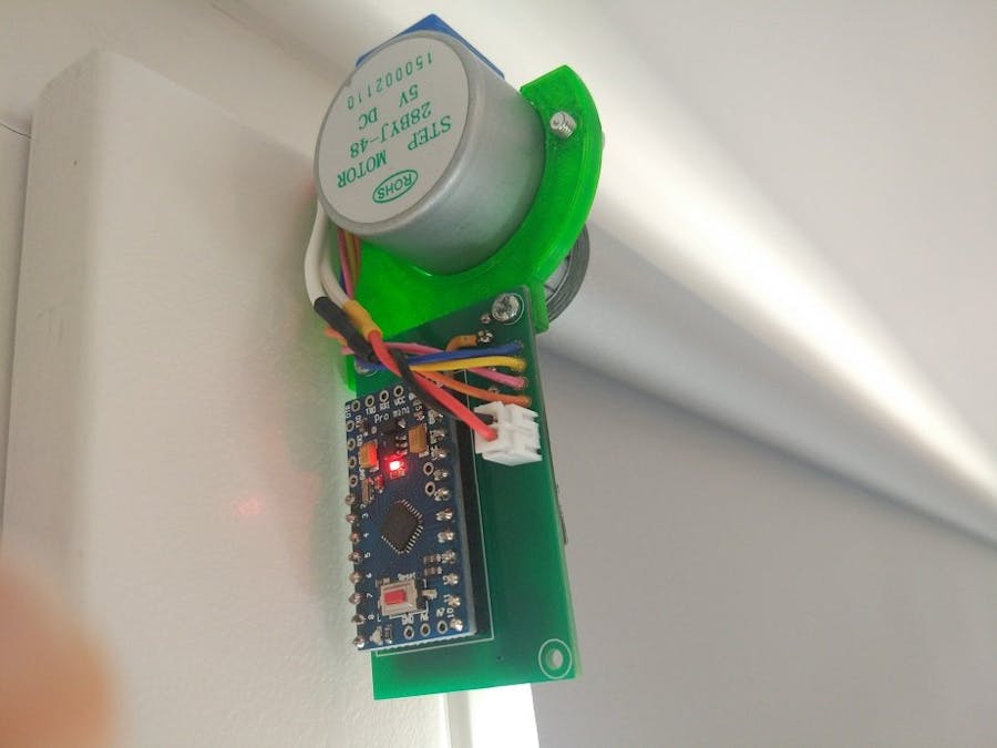
Automatic roller blinds motorAutomatic window roller blinds that can be controlled wirelessly using a NRF24L01 module. Controlled either by a small remote, web interface or RESTful API. Built around an Arduino pro mini and a cheap stepper motor.
How to use itThis assembly replaces the side of the roller blinds with the string. This means they can no longer be lowered or raised manually. You will need to route a wire to each window, in order to supply the 9V required.
The blinds are controlled by either the remote or the web interface or both. For more details on how to control and calibrate the blinds, see the related projects below.
Supported roller blindsI created this project around a Polish brand(STOL-KAR) of clip-on roller blinds I got from here: https://www.leroymerlin.pl/dekoracja-okien/rolety-i-zaluzje/rolety/roleta-zaciemniajaca-blackout-73-x-150-cm-szara-termoizolacyjna, p575054, l929.html
The shaft has an internal diameter of 18mm.You will likely need to modify the 3D printed files to adapt for your model. For easier modification, I included the STEP files.
Limitations and known issues:- The movement can be slow for some. It takes around 50 seconds to lower and 90 seconds to raise the blinds. Using a bigger stepper motor, such as those used in 3D printers can significantly increase the speed, but would require a much bigger power supply.
- When the blinds are not moving, power is not applied to the stepper motor. This means the blinds can be manually pulled, requiring recalibration.
- There is no encoder, so if the motor gets stuck, misses steps or the blinds are rotated manually, recalibration is needed. Also there are no endstops.
For this project you will need a 3D printer, patience, fair soldering skills and some experience with Arduino and Platform IO.
Materials:
- Arduino Pro Mini 3v3
- 28BYJ-48 5V stepper motor
- 0805 1uf SMD capacitor
- 100uF(or higher) 25V SMD type D electrolytic capacitor
- 470uf 6V SMD size C tantalum or type D electrolytic capacitor
- NRF24L01+ SMD module
- A4988 or DRV8825 Stepper Motor Driver module
- 9V power supply (recommended 0.5A multiplied by the number of roller blinds)
- Power supply connector (usually DC2.5/5.5) (optional)
- Wire for connecting power
- Pair of XH 2.54mm 2-pin connectors (optional)
- 3D printed parts found in
3d printfolder. 1x motor adapter and 1x mount(or mount-mirrored)
- PCB
- 2x M2x5 screws
- 2x M3x6 screws
- 2x M3 nuts
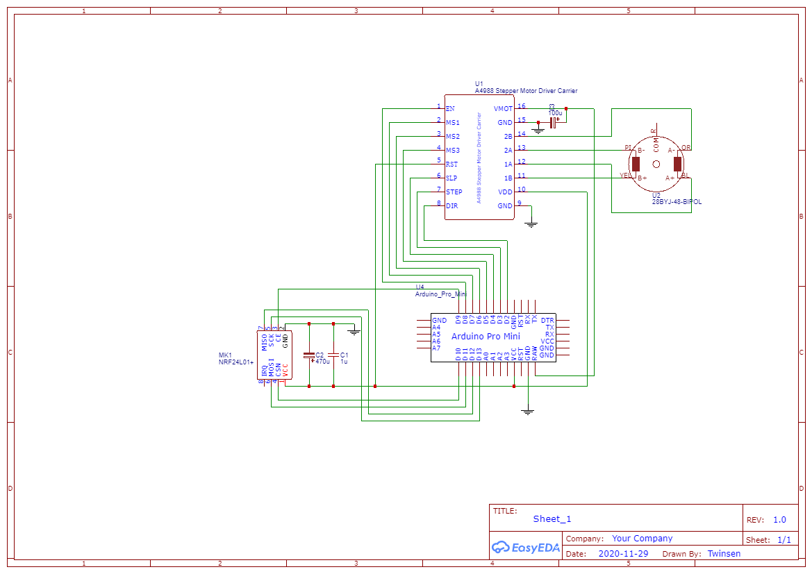
You can find the schematic and PCB in the schematic folder. It contains an EasyEDA project and Gerber files.
Or simply order the PCB from this link: https://www.pcbway.com/project/shareproject/Automatic_roller_blinds_motor.html
Steps:
- Start by converting the 28BYJ-48 stepper motor from unipolar to bipolar. This is done by carefully removing the blue plastic piece and cutting the central trace.
- Solder the pin headers for the Arduino Pro Mini and cut the excess pin length. Pin headers only, otherwise you can't do the next step.
- Solder the A4988 or DRV8825 stepper motor driver module and cut the excess pin length.
- Solder the Arduino Pro Mini to the pin header and cut the excess pin length.
- Solder the rest of the components to the PCB. Use double sided tape for the NRF24L01 module to make sure it doesn't touch the nearby pins.
- Secure the stepper motor to the 3D printed part using M3x6 screws and M3 nuts
- Secure the PCB to the 3D printed part using M2x5 screws. You can choose the orientation and side that is best for you.
- Solder the stepper motor to the PCB as follows: 2B - Orange, 2A - Pink, 1A - Blue, 1B - Yellow. If the motor is facing right, reverse the Blue and Yellow wires; alternatively, you can change the motor direction by changing
STEPPER_REVERSEinConstants.h
- Open this project in Platform IO.
- Open
Constants.hand changeROOM_NUMBERandBLIND_NUMBER. This pair needs to be unique for every window blind. One remote can only control the blinds in one room. The values can't be 0.
- Compile and upload the project. You will need a USB serial adapter.
- Check everything and perform first test. You will need either the remote or the web interface
- Connect the actual roller blinds using the 3D printed motor adapter. Carefully mount it to your window using the original clips or using screws.
- Adjust the height of the motor using the screw on the side, so the blinds are perfectly horizontal.
- Route the wire from the power supply and solder or connect it using XH 2.54mm connectors.
Note: some pictures are slightly different, as I made adjustments and improvements to the PCB and 3D printed parts.
Automatic roller blinds small remoteA small 30x50x20mm remote with 5 buttons, and an OLED screen. Built around an Arduino pro mini.
It has a battery life of a few months.
The remote is used to is used to control the automatic roller blinds motor.
The remote will go into deep sleep after 15 seconds. Press any button to wake it up.
First, you will need to connect the remote to your blinds. To do this, hold the last button for 1 second to enter the menu. Select the room number(according to the ROOM_NUMBER you defined). Navigate to the "Discover" option. Make sure the remote is close to the blinds and simply press ok. The remote will scan of nearby blinds and remember those which have the same room number.
Next you will need to calibrate the blinds so they know what the maximum and minimum positions are. This can be a bit tedious but should be done carefully as not doing the calibration correctly can damage the blinds. Go to the menu and select "Calibrate". Use buttons 3 and 4 to move the blinds up and down. When the blind is in the top position, press button 1 to save it. When the blind is in the bottom position, press button 2 to save it. Press button 5 to move to the next window and repeat until all windows are calibrated. Now everything is set up and you can use the blinds.
On the main screen you can select the window you want to change, the percentage you want to change it to and, using the last button, confirm the change. An X or ✓ will be displayed depending if the command was sent successfully.
To save a preset, move the blinds to the desired positions, enter the menu, navigate to "Save preset", select the preset number you want to save and press ok. To load a preset, hold the corresponding button while on the main screen (hold the first button to load preset 1, etc).
Limitations and known issues:- The range on the NRF24L01 is pretty disappointing when inside a case and covered by a hand. The reliable range is generally limited to one room.
- The remote remembers the last position sent to the blinds and doesn't poll the status. This means that when the blinds are moved (using other remotes, the web interface or RESTful API) the percentage shown on the screen can be out of date.
For this project you will need a 3D printer, patience, good soldering skills and some experience with Arduino and Platform IO.
Since I tried to make it cheap, simple, compact and using simple modules, it requires careful assembly.
Materials:
- Arduino Pro Mini 3v3
- 0805 5.1k SMD resistor
- 2x 0805 1uf SMD capacitor
- 2x 0805 4.7uf SMD capacitor
- 5x 3x4x2mm pushbuttons
- NRF24L01+ SMD module
- 1206 1k SMD resistor
- 1206 4k7 SMD resistor
- HT7333 SOT-89 LDO regulator
- OLED 0.91" 128X32 module
- TP4056 battery charging + protection module
- 601148 3.7V 380mAh LiPo battery. Dimensions are 6x11x48mm. Example link
- 3D printed parts found in
3d printfolder. 5x buttons and 1 of the rest.
- PCB
- 2x M2x5 screws
The PCB needs to be 0.8mm thick(or similar).
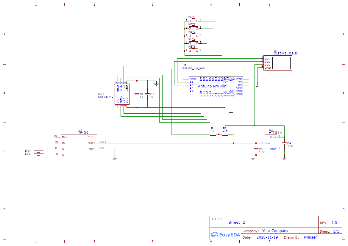
You can find the schematic and PCB in the schematic folder. It contains an EasyEDA project and Gerber files.
Or simply order the it from this link: https://www.pcbway.com/project/shareproject/Automatic_roller_blinds_small_remote.html
Steps:
- On the TP4056 charging module, replace R3 with a 5.1k resistor. This will set set the charging current 235mA.
- Remove R1 and R2 which connect to the LEDs. This will be necessary to connect the wires which will report the charging status to the Arduino.
- Remove the regulator and LEDs from the Arduino. This is required for the low power battery operation
- Remove the switch.
- Open this project in Platform IO, compile and upload it. You will need a USB serial adapter. After assembly it will be difficult to access the programming pins. Alternatively, you can solder a small programming connector.
- Solder the pin headers to the arduino. Make sure you have the correct number of pins. Make sure the pins are facing the side with the components. Because of the compact design, the pins can't protrude more than 1mm from the bottom side. If necessary, solder from the other side.
- Solder the SMD components to the PCB. Note that the switches are very close to each other. Use double sided tape for the NRF24L01 module to make sure it doesn't touch the nearby pins.
- Solder the Arduino to the PCB, upside down. Carefully align the Arduino and PCB so both boards are parallel and the distance between the boards is 6.5mm (including the board thickness)
- Solder the OLED module. The spacing is very tight so I added some insulation to make sure these components don't touch. Add a spacer so the screen is secure and parallel to the board.
- Solder a pair of wires to the power pins on the board and route them between the 2 boards
- Solder 2 small wires to the A0 and A1 pins of the Arduino. They will be used to read the charge status of the TP4056 charging module.
- Remove the protective film from the OLED and carefully place the board inside the case. Use M2x6 screws to secure the board.
- Glue the TP4056 charging module to the "internal part" 3D printed part.
- Glue the 3D printed part to the Arduino board. Make sure it's aligned correctly
- Solder the power wires to the output of the charging module.
- Solder the charge status wires to the charging module. A0 is connected to the R2 pad coming from the IC, A1 is connected to the R1 pad coming from the IC.
- Install and solder the battery.
- Test that it works.
- Close the cover, glue the cover if necessary, glue the 3D printed buttons.
A small NRF24L01 to Wifi gateway. It runs a web server which serves a responsive web interface that allows you to control the window blinds and create schedules. It also has an RESTful API which you can use to control the window blinds from most home automation systems.
Built around an ESP32.
The server is self-contained and does not require any connection to cloud IoT services. If you want to connect to something like Blynk App you will need to implement that connectivity yourself. An internet connection is only required to periodically synchronize the time with a public NTP server.
It handles time, time zones, and daylight savings automatically, simply select your timezone.
It's powered from 5V connected to the micro USB port, but can be powered by anything between 3.5V and 12V.
First you need to set the WiFi credentials. After connecting the gateway to power, wait a bit then press the BOOT button (GPIO0). This will make the gateway go into configuration mode. It will create an AP called "Window blinds WIFI config Portal". After connecting to it, a captive portal should bring you straight to the configuration page, if not, navigate to 192.168.4.1. Choose one of the access points scanned, enter password, click save. Upon successful connection, the gateway will reboot and start the web server.
Go to any browser in the local network and go to windowblinds.local (on Android you will unfortunately need to manually type the IP assigned by your router). Go to the Devices tab and select "Scan for devices". Finally go to the settings page and select your timezone.
If you didn't do so already, you will need to calibrate the blinds so they know what the maximum and minimum positions are. This can be a bit tedious but should be done carefully as not doing the calibration correctly can damage the blinds. Go to the "Devices" tab and select "Calibrate". Press and hold "Move up" or "Move down" to move the blinds. When the blind is in the correct position, press "Set current position as top/bottom". Now everything is set up and you can use the blinds.
RESTful APIAll aspects of the gateway can be controlled though the RESTful API, but for home automation you should only care about these two GET endpoints:
windowblinds.local/setBlinds?roomId=<roomId>&blindNumber=<blindNumber>&targetPercent=<targetPercent>&speed=<speed>
roomIdandblindNumberselect the desired blind
targetPercentsets the percentage to move to (0 - 100)
speed(optional) sets the speed to move with, in percentage of maximum speed (1 - 100)
It returns a json with a "message" field which can be
ok- The command was successful
nrf_send_fail- The radio command was sent but no radio confirmation was received from the window blinds. The command was likely not executed. The window blind is either offline or out of range.
bad_params- some parameters are out of range
missing_params- required parameters are missing
windowblinds.local/getStatus?refreshPositions=<refreshPositions>
refreshPositions(optional). Iftrue, the gateway will first poll all window blinds to check their current target position, otherwise it will simply return the last known position. This is useful if you have other gateways or remotes controlling the window blinds.
- It returns a json containing all the information about the window blinds, schedules, etc.
For the rest of the endpoints, consult the source code.
Limitations and known issues:- The range on the NRF24L01 is pretty disappointing, so when controlling the blinds in multiple rooms, it needs to be well positioned for reliable reception. Alternatively, each room or area can each have it's own gateway.
- Android phones still don't support mDNS, so accessing the web interface needs to be done by manually finding and typing the server's local IP.
- Remember, the S in IoT stands for Security. This project is intended to run only in the local network. If you wish to connect to it remotely, you will need to secure and limit access the connection yourself.
For this project you will need good soldering skills and some experience with Arduino, ESP32 and Platform IO.
Materials:
- ESP32-WROOM-32 bare module
- 0805 1uf SMD capacitor
- 2x 0805 4.7uf SMD capacitor
- 470uf 6V SMD size C tantalum capacitor
- NRF24L01+ SMD module
- 1206 10k SMD resistor
- 2x 6x3.6x2.5mm pushbuttons
- HT7333 SOT-89 LDO regulator
- Micro USB SMD connector Something like this (optional)
- 3D printed case found in
3d printfolder(optional))
- PCB
If you want to use the 3D printed case, the PCB should be around 0.8mm thick.
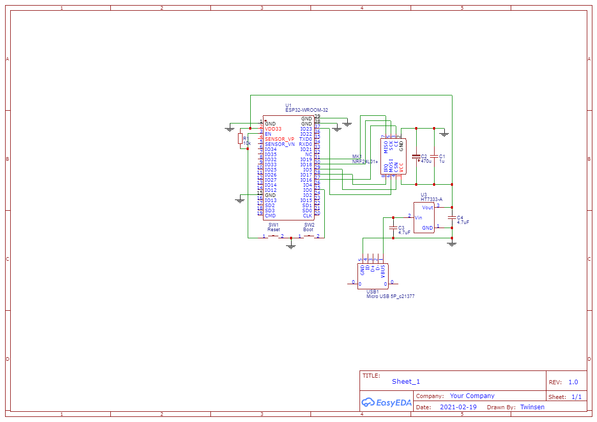
You can find the schematic and PCB in the schematic folder. It contains an EasyEDA project and Gerber files.
Or simply order the it from this link: https://www.pcbway.com/project/shareproject/Automatic_roller_blinds_web_interface.html
Steps:
- Solder the components to the PCB. Note that the microusb connector can be difficult to solder currectly. Alternatively, you can solder wires and supply any voltage between 3.5V and 12V.
- Solder wires to the TX, RX, GND and 3V3 pads and connect them to your USB serial adapter.
- Put the ESP32 in upload mode by holding both RESET and BOOT, then releasing RESET, then releasing BOOT.
- Open this project in Platform IO.
- In Platform IO select
Build Filesystem Image, thenUpload Filesystem Image
- Finally upload the code by selecting
Upload.
- Test that it works.
- Place the board in the 3D printed case (optional).


_3u05Tpwasz.png?auto=compress%2Cformat&w=40&h=40&fit=fillmax&bg=fff&dpr=2)
Comments
Please log in or sign up to comment.