-Active School Traffic Control Devices
Background
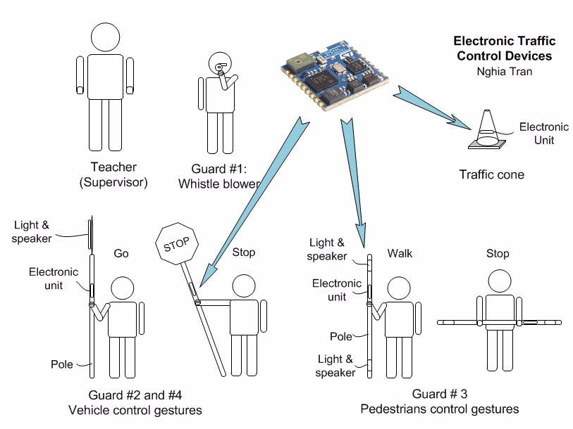
At an elementary school in my neighborhood, there is road guard team that helps kids and pedestrians crossing the street safely and to control the flow of vehicles on the street during the school rush hours, the hours when students come to school in the morning and leave for home in the afternoon. The guard team is formed by a group of four fifth-grader students and a teacher who also supervises the team. Each student is assigned a simple traffic control device, standing at a specific locations to perform sign gestures to control the traffic.
The traffic control devices include: a whistle, a traffic cone, a pole, and a pole with stop sign. The student with the whistle overviews the scene and blow whistle commands. Follow the whistle commands, the students holding poles perform sign gestures to inform the vehicle drivers to go or stop, or letting the pedestrian crossing the street or waiting on the side walk. The teacher holds a notebook and records activities and events.
Limitations
The traffic guard team operates very effective that keeps traffic flow smooth and safe. However, there are some limitations:
(1) When surrounding noises from vehicles or when it’s rain hard, the whistle sound commands becomes uncleared. So the guards have to yell commands and responses across the streets.
(2) On dark or rainy days, the signs and gestures become lack of visibility for the vehicle drivers. The students and pedestrians see uncleared of gesture signs from the guard that tell when it’s safe to cross. This cause more difficulties for the road guard and more risk for students and pedestrians.
(3) The teacher and school offic are not aware of actual environment condition at where the students stand. Bad weather, hot or cold temperature, polluted or poison air may cause harmful to the guards health and others.
(4) The guide teacher takes time to write daily report and records of events during operations.
Solutions
This project contest employs electronics, sensor and wireless technologies to improve the limitations by integrating electronics on these traffic control devices. The main brains of the control devices are Sensor Tiles. The other addtional electronic component may be also user buttons and display, light and speaker, other sensors, GPS, wireless transceiver, and battery power source.
The user buttons are for users (road guards) to input commands and configure the device operation. The user display shows device operation status and user control feedback. The user display can also display communication messages sent and received between the guards.
Speaker and light provide audible and visual signs that can notify drivers and pedestrians.
GPS gives position information of the devices or the guards.
The environmental sensor on the Sensor Tile provide temperature, humidity, pressure, and noise environment condition. The accelerometer, gyroscope, and magnetometer on the Sensor Tile provide orientation that help the guards do gestures more accurate. The orientation of the device can also be used as human gesture data input. A microphone may be used to capture sounds at the scene and human voices.
Micro SD memory is for logging data, commands, GPS and sensors data with the real time stamp. A real time clock can be from the GPS or from internal clock of controller.
The wireless Bluetooth transceiver links traffic control devices, allowing a control device can send and receive data to/from other traffic control devices and other electronic in RF range.
The microcontroller STM32 on the Sensor Tile processes and controls all data and signals on the device. The controller also manages wireless Bluetooth communication.
Battery provides power for all electronic circuits. It may contain battery charging circuit.
54 days left (23 Aug 2017)
Until now there is no messages yet from contest organizer announce who will get the free SensorTile Development Kit. The website status still appear “Awaiting review”. I’m a little worried about my project proposal. I’m also worried about remain time until due on 15th of October. Only 54 more days to go.
So, yesterday I ordered a SensorTile Development Kit and additional Wi-Fi module that I may use it in this contest. Today the kits arrived. Recently there is an electronics distributor offers free delivery overnight if order over $20.
The price for the SensorTile Development Kit, part number STEVAL-STLK01V1 is about $80.
The price for the Wi-Fi module, part number X-NUCLEO-IDW01M1 is about $25.
If not purchase the whole SensorTile Development Kit, the SensorTile itself can be purchased separately with price about $35. The part number of the SensorTile is STEVAL-STLLS02V1.
There is a website I like when looking for prices, the www.findchips.com
Below is list of some of the electronics distributors:
Arrow Electronics - www.arrow.com
Avnet - www.avnet.com
Chip1Stop - http://www.chip1stop.com - An Arrow company
Digi-key Electronics - www.digikey.com
Farnell - http://grh.premierfarnell.com
Future Electronics - http://www.futureelectronics.com
Mouser Electronics - http://www.mouser.com
Newark - www.newark.com
Verical - www.verical.com - An Arrow company
53 days left (24 Aug 2017)
Today I’m going to open the SensorTile Development Kit and check the SensorTile and other things come with the kit.
The main part of the SensorTile Development Kit is the SensorTile, part number STEVAL-STLC02V1. The SensorTile is the small square piece has dimension of 13.5mm x 13.5 mm. It is comprised of various MEMS sensors (Accelerometer, Gyroscope, Magnetometer, Pressure sensor and Microphone), a wireless Bluetooth transceiver with processor and chip antenna, and a low-power microcontroller STM32L476.
Most of the components are populated on the top of the board as shown. The 18 half-moon copper pads exposed on two sides are pinouts. These pinout includes power supply, programming ports, and common peripheral interfaces such as UART, USB, I2C, SPI, ADC, GPIO. The half-moon pads can be soldered with wires or PCB pad. The bottom of the board has a tiny connector provides an optional interface, allowing quick connect to a board.
Below is the block diagram of the SensorTile. We can consider the SensorTile comprised of four different circuit: (1) Sensor circuit in green, (2) Wireless Bluetransceiver circuit in aquablue, (3) System and controller in skyblue, and power supply circuit in orange.
There are three boards in the kit:
1. SensorTile board
2. Cradle board
3. Cradle expansion board
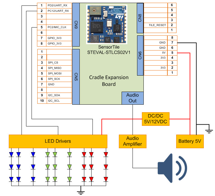
For development and evaluating, the SensorTile can be quick connected to the Cradle Expansion Board with connector as the location shown. The power can be provide via the micro USB connector. The Cradle Expansion Board provide additional feature of audio output with SPI DAC. Other peripheral are available at the Arduino connector.
Figure below shows block diagram of SensorTile combining with the Cradle Expansion Board.
The SensorTile board can be also combined with the Cradle, battery and a plastic case (not shown) to form a complete stand alone sensor unit, and it’s good for portable battery run evaluation. This combination requires the SensorTile to be soldered on the Cradle. Once soldered it’hard to separate the SensorTile from the Cradle.
Figure below shows block diagram of SensorTile combining with the Cradle
Run the Preloaded Demo + Run ST BlueMS App Android
With Android phone, install app ST BlueMS by STMicroelectronics from the Google Play Store
Open the ST BlueMS
Device List
BM2V220 C0:7A:28:31:51:48
When not connected the Red LED on the SensorTile blinking. As soon as the phone is connected to the SensorTile the Red LED stop. When disconnect, Red LED blinking.
Plot Mic Level: OK Accelerometer: OK Gyroscope: OK Magnetometer: OK Pressure: OK Temperature: OK
Serial console: Select Temperature: print pressure and temp values Select pressure: print pressure and temp values Select Acc, Gyro, Mag, Mic: print status On/Off
Open debug console
RSSI: -44[dbm] (1 ft apart)
Other Examples
Download software example STSW-STLKT01 package from http://www.st.com/content/st_com/en/products/evaluation-tools/solution-evaluation-tools/sensor-solution-eval-boards/steval-stlkt01v1.html?icmp=tt4307_gl_bn_oct2016
Unzip the STSW_STLKT01. The STSW_STLKT01 contains all files and dependencies for three example project:
1. DataLog
2. BLE_SampleApp
3. AudioLoop
Run the Datalog example and Putty terminal
Run the BLE_sampleApp example and Putty terminal
Run the AudioLoop example and Putty terminal
The AudioLoop example: The microcontroller takes the audio stream from the MEMS microphone on the SensorTile and paste to the audio DAC chip on the Expansion Cradle. Audio output can be heard using a headphone plugging to the audio jack.
________________________________________________________
Active Traffic Controller Stick - 25 Oct 2017
Software
Hardware


Comments
Please log in or sign up to comment.