


Hardware components | ||||||
| × | 2 | ||||
| × | 5 | ||||
| × | 1 | ||||
| × | 2 | ||||
| × | 1 | ||||
| × | 1 | ||||
| × | 1 | ||||
| × | 1 | ||||
| × | 1 | ||||
| × | 1 | ||||
 |
| × | 1 | |||
 |
| × | 1 | |||
Software apps and online services | ||||||
| ||||||
Hand tools and fabrication machines | ||||||
| ||||||
| ||||||
 |
| |||||
 |
| |||||
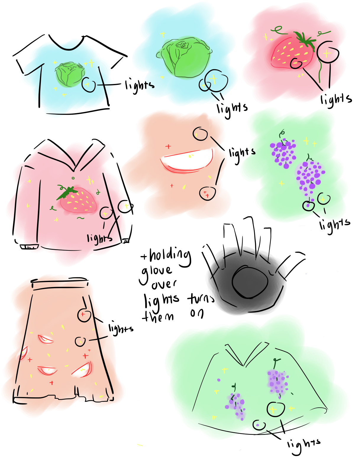
The design of this product is inspired by seeds in fruits or the core life. The place of the lights themselves match up with where the seeds would be on strawberries, grapes, and so forth.
For lotus flowers, the stamen is where the plant gets pollinated, so that's why the lights are focused there.
Though the designs could work in various ways and on various types of clothing, we chose to work with a poncho-type garment to allow for ease of movement and wearability. It is already a piece that would be layered, so it's easier to implement the wiring system with this rather than, say, a normal tee shirt.
We also worked with a traditional Vietnamese ao dai because this aspect of layering is present there as well, and the flow of the garment allows for more movement in design that isn't as present in more static pieces of clothing.
Wireless energy transfer technology is more mature nowadays. It’s been used for near field communication (NFC), charging phones, charging vehicles, and delivery power for one device to others without using electric conductive wires or cables. This techfashion project, my daughter and I, employs the technology to integrate lights on clothes.
The wireless transfer energy is based on the alternation of electromagnetic fields. When the coil-1 is fed by an electric alternating current (AC) source, it generates an alternate electromagnetic field in the air in a region around it. If the coil-2 is placed in the magnetic field region, it is induced, and a voltage appears at the two terminals of the coil-2. The voltage of the coil-2 supplies power to the load. So we have the electrical energy transferred from the source, to coil-1, through the air, received by coil-2, and to the load.
The distance between the coil-1 and coil-2 depends on the strength of the source, the alternating frequency, and the coils configurations. The coils configuration can be considered such as number of turns, turn diameter, turn alignment, wire size. The bigger of the turn, the longer distance energy transferred.
Most of the power sources available like batteries are not -very efficient for energy transfer in the air. Therefore an AC generator circuit is needed to convert a DC power source to an AC source with a desired frequency before feeding to the coil-1. At the coil-2, AC induced voltage is filtered before feeding to an electronic device. The electronic device can be an audio/video device, controllers, display, and for this project are LEDs. The LEDs can be a single light spot, string of light, or array of light.
Wireless LED kitThe Wireless LED kit made by Taidacent includes a wireless energy transmitter and multiple energy receiver LEDs. When the transmitter is supplied with 5VDC, the transmitter emits wireless energy in the proximity region inside and outside the big coil. When the receiver LEDs are placed in the proximity region, the receiver LEDs are lighted up.
The block diagram explains how the wireless LED works. The pulse generator generates square wave signals to feed to the pulse driver. The pulse driver acts like a switch to turn on and off the power to the transmitter (Tx) coil. When the pulse is HIGH, the switch is close, and the Tx coil is energized and when the pulse is LOW, the switch is open, and the Tx coil is de-energized. The process energized/de-energized the Tx coil causes the change of magnetic field around the Tx coil. The filter can be considered a matching circuit which helps the Tx coil to emit maximum energy into the air. The wireless receiver LED includes a receiver (Rx) coil, a filter, and a LED. When placed in the electromagnetic field region of the Tx coil, the Rx coil is induced. The voltage output of the Rx coil is filtered to supply power for the LED to light up.
For references, the schematic of the wireless LED kit is drawn back from the transmitter and receiver boards. The original of this material may be referred to Taidacent (Support: Bill Yuan, billyuan12@gmail.com). The U1 is the square wave pulse signal generator, U2 is the pulse driver, and capacitor C2 is the filter. The frequency of the pulse can be adjusted by changing the value of resistor R1. The frequency of the square wave signal measured is around 225kHz. The capacitor C2 and the Tx coil forms a LC tank circuit with resonance frequency is calculated as below.
The resonance frequency of the LC circuit is around the square wave signal frequency. There may be some error in measurement technique and meter accuracy. When the frequency of the LC resonance circuit and the square wave pulse are matched, the wireless energy emitted by the Tx coil is the most efficient.
On the receiver, the Rx coil and the 220pF capacitor also form a LC tank circuit with resonance frequency as calculated below.
Similar for the receiver, the matching of resonance of the LC circuit of the receiver allows the most wireless energy to be received.
The power consumption should be measured and calculated to see if it’s suitable for implementing the wireless LED on clothes. At 5VDC power supply, the whole kit which includes a transmitter and 10 receivers draw around 90mA, so the instance power consumption is 450mW. A small rechargeable 5000mAh battery pack can provide power for the LED kit to run in 55 hours. That’s very good. If a wireless LED kit is used on a cloth, the user can wear it with the LED on for several times before the battery needs to be recharged.
This is the current consumption chart for 1 to 30 LEDs placed inside the coil. When no LED is present inside the coil, the current is about 80mA or 400mW. When 10 receiver LEDs are present, the current is 85mA or 425mW. With 30 receiver LEDs presented, the current is 94mA or 470mW.
See the video about the wireless LEDs kit here.
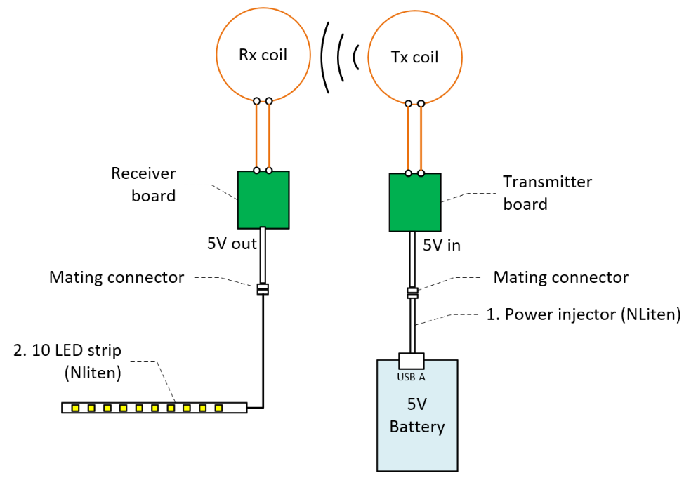
Energy Transfer Kit
Above is another form of wireless energy transfer. Instead of receiver LEDs, this kit configuration is the energy receiver. A 5V DC is injected to the wireless transceiver board and a 5V DC is extracted from the wireless energy receiver board.
The power injector from NLiten allows LEDs strip to be connected to a common battery pack via USB-A port. The power injector also provide connection of the LED strip to a controller. The controller can send stream out serial data control the color and brightness of individual LED on the strip.
10 LED Strip (NLite)Each LED on the strip contains four color element: Red, Green, Blue, and White. Each LED can be controlled color and brightness independently using serial data goes through LEDs.
Multiple LED strips can also be easily cascade with each other via end connectors.
The Power Injector is designed for quick connect and install LED strip to USB battery pack.
Design 1 - Individual LEDs receiver
Though the designs could work in various ways and on various types of clothing, we chose to work with a poncho-type garment to allow for ease of movement and wearability
Our design for the light on a cape comes in a two-layers set. The receiver LEDs can be mounted on the outside of the cape in desired positions. Each receiver LED can be made water proofed and glued on fabric with transparent glue.
The inner layer shirt is designed for placing the transmitters, wiring, and battery. For design, the LEDs are scattered across the cape surface and may need to have two transmitters to light up all the LEDs. The transmitters can be placed inside the pockets. The pockets hold and secure the transmitters inside. The power from the battery pack is conducted to the two transmitters at the power bus. The power for the transmitters can be turned on/off using a switch on the battery pack or plug/unplug USB connector to the battery pack.
The transmitters and battery and maybe the wiring can be quick and easy to put in and take out of the pockets when needed, as like washing.
One inner design can work with a variety of outer art designs. However, since the locations of the transmitters are fixed, the LEDs should be mounted or glued hover above around the transmitter coils.
The outer layer can be another cloth form like jacket, dress, shirt, craft, or any wearable clothes.
This design uses an LED strip placed inside of the cape outer layer to glow the fruit as the back light. The wireless transmitter circuit is embedded on the inner layer and the wireless receiver circuit is embedded on the outer layer of the cape.
This design embedded a battery, LED strip, and cable on the inner layer shirt. The LED strip should be positioned and oriented to glow the fruit section on the outer layer cape. The garment region where the fruit is located can be made with film type, letting more light get through to gather more attention.
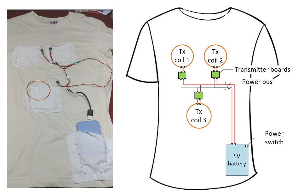
Cape Inner Layer
Three transmitters are integrated on an inner T-shirt. The 5V from the battery pack are distributed to three transmitters at a power bus. The transmitters and the battery can be held in pockets and they can be removed when needed.
The wiring can be made more organized for more neat and secure.
Cape Outer Layer
Our first art we chose to work with is lotus flower as embrace of its remain untouched character as it emerges from the mud.
The garment is a thick warm flannel. Brownness color represent for the mud. A neighbor hood tailor helped to make the cape and my partner, Tammy, painted the flower. After painting, LEDs receivers are glued at yellow sport locations.
The photo above is testing laying the cape over the T-shirt. The LED receives scattered in multiple locations of the cape front.
Inner Layer T-Shirt
Outer Layer
The LED strip can be used to glow the lotus and yellow apricot flower from underneath employing design-2 and design-3 described in the previous sections. If a controller could be used, the LED strip can be controlled to make the light dance with ambient music or voice. A mini audio system can be added on the inner layer, producing sounds and music, interesting to audiences.
See the video demonstration here on YouTube
The video demonstrated design using wireless LED as mentioned in design 1. The same idea of putting on and taking off clothes can be applied for design 2 and design 3.

Comments
Please log in or sign up to comment.