Is this one I hear you ask...No! (Same but better display w/o linux pc for $20)
Although "mostly"... The Pi Zero is 15$, the Sds011 is 15$ and the Si7021 is 3$.
Unfortunately while exploring the Sds011 and surrounding literature I have found that it doesn't hold up well when compared with accurate and expensive particle sensors. It does however do relatively well in the <2.5um particle count and is certainly useful for general measuring of environment or thresholds.
[I'll post the link if I can find it, but it was a comparison of the SDS011 and the Plantower 7003? + 5003?]
InspirationI wanted to please a friend, an environmentally conscious friend who is concerned about mould spores in the air (from damp), additionally he is an occasional smoker and lives on a fairly popular city road, so he's keen to see what's present in the air as far as concentration and air quality go.
To this end I have obtained:
- an additional Raspberry Pi Zero WH (zero with wifi and headers - I believe the only version allowed for multiple purchases),
- repurposed an old LCD screen (JHD162A),
- a particle sensor that I had finished experimenting with (Nova Fitness Sds011),
- and one of my temperature and humidity sensors (Si7021) that is no longer fit for my purposes (wont accept 100% relative humidity / condensation).
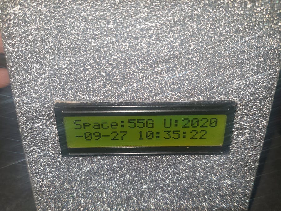
It's all packaged "relatively" neatly in a lovely glitter covered cardboard box (cheap and easy to cut/modify).
I made sure to test each component/system(example code+component) in isolation before introducing them all together, both physically and in terms of software.
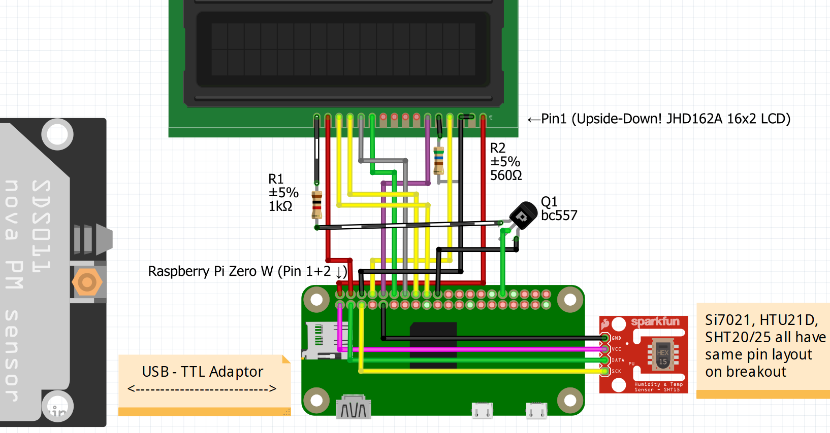
BuildThe SDS011 particle sensor includes a USB to TTL serial adaptor and connector cable (for between the sensor and adaptor), but unfortunately the Pi Zero doesn't have a full size usb socket, so I attached a micro-usb male plug to the adaptor board and hot glued it for stability. This then shows up on the pi zero under the device file /dev/ttyUSB0 which is used in the script.
The Si7021 is an I2C sensor, so we need to enable I2C on the pi.Running sudo raspi-config and selecting interfaces, i2c, enable, will solve this.Running sudo apt get install i2c-tools will allow us to test the i2c connection (with the command i2cdetect 1 and answer Y to scan the i2c bus). The sensor shows up as 44 or 40 (or check your sensors datasheet for default i2c address).
Follow the wiring explanation/guide on this site for the lcd (we use 4bit mode):https://www.raspberrypi-spy.co.uk/2012/07/16x2-lcd-module-control-using-python/
[Archive.org WayBackWhen machine link: http://.....]
I have rearranged the pins to suit my preferences (one line close to one end) but follow the same order as in the guide.
You'll notice I've added a transistor setup to control the brightness via PWM, initially I had full brightness however it is more pleasant to have a gradual change throughout the day.
Our device should always be up to date, software updates are released to protect the world against software problems, so we will set the device to run updates using crontab. It will still need to be manually rebooted now and then (assume the user unplugging it now and then being sufficient)
I've added the two lines listed below to the file /etc/crontab but you may wish to do things differently. They cause hourly update attempts. I use nano to edit files (sudo nano /etc/crontab) then save with ctrl+o, and exit with ctrl+x
25 *    * * *   root    apt update
35 *    * * *   root    DEBIAN_FRONTEND=noninteractive apt upgrade -yq
We need a couple of things, so lets install them as follows:
sudo apt install python3 python3-pip i2c-tools python3-rpi.gpio git
sudo pip3 install adafruit-circuitpython-si7021 RPLCD blynklib
Now we can get the code and test it, then if we want we can set it to autorun by copying the .service file to /etc/systemd/system/
cd /home/pi
git clone https://github.com/tyeth/john_air
chown -R pi:users ./john_air
cd john_air
sudo cp john_air.service /etc/systemd/system/
sudo chown pi:users /etc/systemd/system/john_air.service
sudo chmod a+rx /etc/systemd/system/john_air.service
python3 ./main.py
At this point it should work. You'll want to edit main.py and put in your own blynk authentication key and setup your own blynk project to display the data (I use virtual pins 0-5)
pin_TEMP = V0
pin_HUMIDITY=V1
pin_ppm25 =V2
pin_ppm10 =V3
pin_aqi25 =V4
pin_aqi10 =V5
This should result in the script booting up, and following the following procedure:
- Cycle display brightness to indicate the PWM works.
- Check free space, and last run of APT upgrade, display on LCD and check time of day to update PWM for backlight
- # Depending if not bootup or every 5 runs then start cycle below
- Display date/time
- Check Si7021 sensor and read latest value
- Check PPM sensor, wake up and read latest value
- Display latest values for temperature, humidity and PPM < 2.5/10 um (ug/m3)
- Log data to SD card (55Gig remaining so a few years), and Blynk
- Repeat cycle (check disk and APT every 5 cycles)
Everyone loves a nice infographic and graph, so that's what we got. Provided by blynk (you seem to get limited credits to put components on your dashboard but it's just enough for one smart graph, a colour gauge and some data values/labels)
I would probably not choose blynk again as it's overly limited for anything beyond a very simple project. The work required to create something similar can be a lot (influxdb+grafana) so blynk definitely has it's advantages.
The main thing is that all the readings are captured to a csv file on the SD Card, plus the smartgraph in Blynk allows you to request an export of the data by email.
PWM
Since doing the initial write-up I've ended up adding PWM to control the LCD backlight because full blast at night was a problem.
AQI - Air Quality Index
I also designed the original offline version around a colour based dashboard via someones AQI tutorial and adding the legend for AQI, a plotly chart and some css. The idea was to use the colour / description system https://www.airnow.gov/aqi/aqi-basics/ to also say what the ppm count meant.
I have finally got around to adding this, it meant a UI redesign, with one page of info per parameter, page1: temp/hum, page2: AQI + ppm<2.5um, page3: AQI + ppm<10.
Doing things properly / Avoiding blue smoke...
Apart from that, mostly just that I should have modelled the circuit for the transistor setup and measured the backlight current consumption, this would allow me to calculate what current was going through the GPIO pin instead of just blindly hoping for the best. Also there is occasional dimming on the lcd as a sensor is read so a capacitor or ten could have helped. Oh-well, I'll let you know if I get around to it :)


_3u05Tpwasz.png?auto=compress%2Cformat&w=40&h=40&fit=fillmax&bg=fff&dpr=2)
Comments
Please log in or sign up to comment.