


Hardware components | ||||||
 |
| × | 1 | |||
 |
| × | 1 | |||
 |
| × | 1 | |||
*DISCLAIMER*
I'm not an expert on Kalman Filters. Just sharing my story. Maybe it is helpful for someone. If you have suggestions or ideas, feel free to leave them below in the comments.
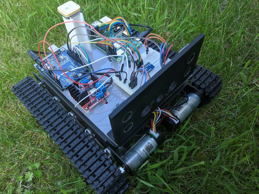
Using a Kalman Filter for localization?I made a robot that navigates outdoors. It uses waypoints to navigate. To do that it needs to know where it is. And that is where the big problem starts. Knowing were something is, isn't easy. GPS seems obvious, but it is imprecise. Its because you need to move to get a decent position fix. And when there are big objects like trees and houses nearby you get something called "multipathing".
Use an IMU? Most small IMU's are not very consistent. You don't always get the same speed readout. On ruff terrain (grass) it is even worse.
Kalman Filter? A Kalman Filter can do something called "sensor fusion". It combines the output of multiple sensors into one consistent output.
Kalman FilterA Kalman Filter can be used as a filter/smoother or a sensor fusion algorithm.
Kalman Filters seem well documented on the internet. But they are NOT.
The problem is; most good explanations stay to theoretical. They fail to explain what a certain thing means in practice.
The basics of a Kalman FilterThe Kalman filter works with probability. The likely hood of where the current 'state'/position of the 'system'/robot is.
The likely hood of where the current position of the robot is.
The likely hood of what the current state of the system is.
The likely hood is represented by the 'normal distribution'.
This likely hood can be compared to the location circle of Google Maps. "It is likely that you are within this blue circle."
There are some good explanations on the internet. This one illustrates it. https://www.bzarg.com/p/how-a-kalman-filter-works-in-pictures/
Let's get practicalIn programming (Python) is the Kalman filter defined in matrixes. These matrixes contain the configuration of your Kalman filter.
There are the following matrixes:
- X: state (output)
- P: state noise
- F: state-transition model
- U: prediction input
- B: input model
- Q: process noise
- Z: update measurements (input)
- H: observation model
- R: observation noise
I used this Python class to do the calculations. (Numpy imported as np)
import numpy as np

class KalmanFilter(object):
    def __init__(self, F = None, B = None, H = None, Q = None
                , R = None, P = None, x0 = None):

        if(F is None or H is None):
            raise ValueError("Set proper system dynamics.")

        self.n = F.shape[1]
        self.m = H.shape[1]

        self.F = F
        self.H = H
        self.B = 0 if B is None else B
        self.Q = np.eye(self.n) if Q is None else Q
        self.R = np.eye(self.n) if R is None else R
        self.P = np.eye(self.n) if P is None else P
        self.x = np.zeros((self.n, 1)) if x0 is None else x0

    def predict(self, u=0):
        self.x = np.dot(self.F, self.x) + np.dot(self.B, u)
        self.P = np.dot(np.dot(self.F, self.P), self.F.T) + self.Q
        return self.x

    def update(self, z):
        y = z - np.dot(self.H, self.x)
        S = self.R + np.dot(self.H, np.dot(self.P, self.H.T))
        K = np.dot(np.dot(self.P, self.H.T), np.linalg.inv(S))
        self.x = self.x + np.dot(K, y)
        I = np.eye(self.n)
        self.P = np.dot(np.dot(I - np.dot(K, self.H), self.P)
                        , (I - np.dot(K, self.H)).T) + np.dot(np.dot(K, self.R)
, K.T)To start configuring your matrixes you need to ask yourself two questions.
- What do you want? What output must the Kalman Filter give? In my case, I need to know the position of the robot.
- What do you have? What input data is available for the Kalman Filter? this can be GPS position, IMU accelerations,... You have more input data then you think! Most GPS modules give bearing and speed. Try to get all the data out of your sensors.
The x matrix is the output of the Kalman Filter. If you want to predict the position, you fill in the XYZ position.
Xpos
Ypos
Zpos
Knowing the velocity is handy for calculating the position. So I filled the XYZ velocity's in.
Xvelocity
Yvelocity
Zvelocity
The final result of the X matrix is:
There are 2 inputs. The U matrix for the state prediction. The Z matrix for the state update.
When you run the Kalman Filter, you start by making a prediction. When you have made a prediction, you can do 2 things: make another prediction or update the model.
- The IMU has a read frequency of 100Hz.
- GPS has a read frequency of 20Hz.
I used the IMU as input for the state prediction (U matrix). The lower frequency GPS for the state update. Your Kalman Filter can make more predictions than updates. That's why you take the high read frequency input as state prediction input.
FramesBefore we start feeding data to the Kalman filter. We must first correctly format the data. The accelerations must be transformed into the correct frame and correct scale. There are 3 frames.
- GPS global frame; Longitude and latitude
- Local positioning frame; The local frame where the Kalman filter works in. It has a reference point (base station) and a direction (Nord).
- Body frame; The frame where the IMU works in. It is the orientation of the robot relative to the local frame.
import math


def GPS_velocity_to_local(gpsVel, angle):
	vel = gpsVel
	Vx = math.cos(angle) * vel / 3.6 # 3.6 for km/h to m/s
	Vy = math.sin(angle) * vel / 3.6 # 3.6 for km/h to m/s
	v = [Vx, Vy, 0]

	return v

def GPS_position_to_local(gpsRefPosition, gpsCurrentPosition):
	lon1 = gpsRefPosition[0]
	lat1 = gpsRefPosition[1]
	lon2 = gpsCurrentPosition[0]
	lat2 = gpsCurrentPosition[1]

	dx = (lon1 - lon2) * 40000 * math.cos((lat1 + lat2) * math.pi / 360) / 360 * 1000
	dy = (lat1 - lat2) * 40000 / 360 * 1000

return [dx, dy]import numpy as np
import math
def IMU_acceleration_to_local(bodyRotation, acceleration):
eulXYZ = bodyRotation
y = eulXYZ[0] #yaw
p = eulXYZ[1] #pitch
r = eulXYZ[2] #roll
mes = np.array([
[acceleration[0]],
[acceleration[1]],
[acceleration[2]]
])
c = math.cos
s = math.sin
# Direction cosine matrix
trans = np.array([
[
[c(y)*c(p), c(p) * s(y), -s(p)],
[c(y)*s(p)*s(r)-c(r)*s(y), c(y)*c(r)+s(y)*s(r), c(p)*s(r)],
[c(y)*c(r)*s(p)+s(y)*s(r), c(r)*s(y)*s(p)-c(y)*s(r), c(p)*c(r)]
]
])
out = np.dot(trans, mes).tolist()[0]
out = [out[0][0]*-1, out[1][0]*-1, out[2][0]]
return outThe U matrix is the main input matrix of the Kalman Filter. It is used in the state prediction. In the U matrix, it is best to use your high read frequency input data. In my case: The IMU data. This matrix is not required. If you don't have a second sensor.
The IMU provides accelerations in m/s. We can use this acceleration for updating the position and the velocity.
Before we can use the acceleration. We need to translate from the body frame to the local frame. We can use the absolute orientations from the IMU. By using the Direction cosine matrix we can translate the acceleration between the 2 frames.
Our U matrix will look like this:
Ax
Ay
Az
0
0
0
Ax, Ay, and Az are the XYZ accelerations translated to the local frame. The 3 zeros are additional input that we don't use. I will come back on it later.
The B matrix contains the relation between the input (U) and the output (X). It tells the Kalman Filter how the U matrix affects the state (X matrix/output).
On the left, we have the previous state (X matrix). In the middle, we have The B matrix. On top, we have the input U matrix. On the right, we have the future state (output/X matrix). We want to influence the future state/output with our measurements(U matrix/input).
The relation between the acceleration and the position is the 2nd derivative of the acceleration.
deltaTime²/2
The relation between the velocity and the acceleration is delta-time.
The final result will be:
The Q matrix contains the variance of the input from the U matrix. It contains the usual mistake of your input. A very small number means that your sensor/input accuracy is high. A high number means that your input is very inaccurate. Don't use 0 unless it is unused.
You fill in the variance of your input on the diagonal of the matrix.
Finding the variance of your input. The variance of your sensor can be obtained from the datasheet of your sensor. But, most of the time this is wrong. There are two other ways to obtain the variance.
- Measure the sensor reading while your system is in normal operation. Then at the same time, make a measurement with a better sensor to compare with. This way is not very practical. Unless the measurement that you use to compare with is very precise.
- Measure the sensor reading while your system is idle/not moving. And compare the sensor reading with 0. This will give you a variance. Not the best one.
The Q matrix can look like this:
The Z matrix is the second input matrix. It is used in the state update. Normally you put your low read frequency sensor date here.
The Z matrix contains the GPS measurements. GPS provides a location fix longitude and latitude. The long and lat are translated to the local frame in XYZ coordinates (in meter). The GPS also provides velocity. These are relative to the Nord and are in km/h. We convert the velocity to m/s. The Z matrix will look like this:
PositionX
PositionY
PositionZ
VelocityX
VelocityY
VelocityZ
The H matrix is similar to the B matrix. It contains the relation between The Z matrix input and the output (X matrix). It is the same process to fill in the H matrix than filling in the B matrix.
In this case, GPS input has a 1 to 1 relation to the output (X matrix). The H matrix is a unity matrix.
The R matrix contains the variance of the input from the Z matrix. You use only the diagonal to put the variance in. The variance can be derived in the same way as the variance of the Q matrix.
I measured the deviation of the GPS while the robot was standing still. This will provide you with the variance of the GPS. In my case the R matrix looks like this:
The F matrix contains the relation of the data from state to state. For example, the velocity affects the position by delta-time.
We want the current position en velocity in our future state. And we want the velocity to affect the position by delta-time. To propagate the current state to the future state we will start off with a unity matrix.
Now we want the velocity to affect the position by delta-time.
The P matrix contains the variance of the current state (X matrix). The Kalman filter will update the values by itself. You can initialize it as a unity matrix. Or you can use a P matrix from a previous run. When you use a P matrix from a previous run. The Kalman filter will be more accurate at the beginning.
- The Kalman Filter probably won't work the first time. This is because the variance is not constant in the real world. The variance of a sensor is constantly changing. The GPS module is more accurate when the robot is moving. When the robot is idle the acceleration is zero. This is very precise. Because we know when the robot is moving. You know when your motors are receiving power.
- Optimizing the Kalman Filter is very important. tweaking the variance while te Filter is running is a must.
- The ratio between the covariance matrixes (Q and R) is more important than the number.
- Overwriting the input when you know it is wrong is a good idea. If you know the real number, overwriting it can be helpful.
A Kalman Filter is a good algorithm for filtering noise and combining sensors. But, it has its limitations. It's not magic. If your sensor data is rubbish the result of the Kalman Filter will not be much better. The inconsistency of the IMU is a big problem. The multipathing of the GPS module is a problem. Some can be resolved. You can use more high-quality sensors. But it gets expansive very fast.
In my project. The Kalman Filter improved the localization. But I never got it working as I wanted. Getting an accuracy lower than 1 meter is hard.


Comments
Please log in or sign up to comment.