This tutorial participates in the "INSTRUMENT CONTEST" so if you liked it, please vote for it.
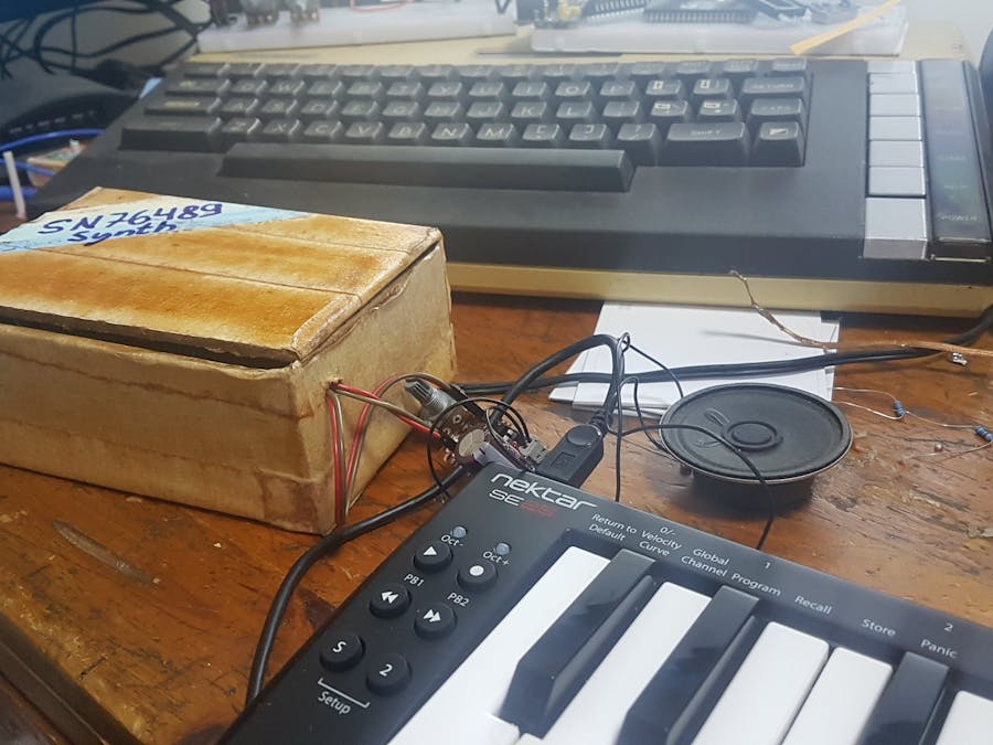
Ever wanted to build your own synthesizer based on old chip-tunes from the 80's? Play simple polyphonic tunes that sounds just like these old Sega Master System and Megadrive video games sounded like?
I have, so, I ordered a few SN76489 chips from ebay and a midi host interface and gave it a shot. Well, it wasn't a walk in the park for me, but, I enjoyed every moment.
First I learned how to directly interface the SN76489 and make some noise with it. There were some confusing elements to this, but, with the help of The Oddbloke Geek Blog and a few other examples, together with the chip specification document I was able to develop a simple arduino library.
Next, I had to learn how to interface a midi keyboard with a USB mini host shield. This wasn't so hard, as there is some documentation available, and good libraries exist with clear examples.
Once I understood how to control the chip and how to interface my USB midi keyboard, the only thing left to do was to write some code that would wrap all of this together and allow me use the keyboard to control the chip.
Along the way, I learned that sounds with frequency lower than those I tried to generate for 0x2f midi notes didn't sound right, so, I decided to use that to allow sending noise to the noise generator for any midi notes between 0x28 and 0x2f and also allow play notes with an oriental arab touch to it for anything lower than midi 0x28.
Looking backwards, it was a lot of fun and very interesting to build.
I hope you find it as fun and interesting as I did and that if you build one yourself, you'd be kind enough to share some pictures of it.
If you liked this project, please vote for it down below to help win the contest it participates in.
Supplies:1 x performance board | https://ebay.us/svA4z4
1 x arduino nano | https://ebay.us/ZyEFNp
1 x USB mini shield | https://ebay.us/t1zy0v
1 x SN76489 sound chip | https://ebay.to/2QrHl1C
1 x shift register 595 | https://ebay.us/aaaj8p
1 x crystal oscillator of 4MHz | https://ebay.us/DSvTHO
1 x 5V voltage regulator 7805 | https://ebay.us/XQeM0Q
1 x heat sink for the voltage regulator | https://ebay.us/6R6Fpf
3 x 10uF capacitors | https://ebay.us/xkLbn4
wires | https://ebay.us/pnm2BH
1 x red LED for power | https://ebay.us/PMbUfY
1 x 220 ohm resistor to limit the LED current flow | https://ebay.us/zokHtc
1 x power connector for 12v power supply | https://ebay.us/qjbesJ
1 x on/off switch | https://ebay.us/cS0wwv
a suitable box (I built mine from an old drawer that was resting in my storage for years)
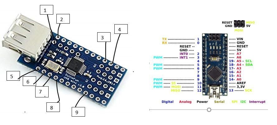
Step 1: Preparing the USB Mini Host Shield to Drive a 5V Midi DeviceSince the USB mini host shield operates on 3.3V and the USB midi keyboards I use require 5V, it is required to adjust the shield's output voltage by cutting the 3.3V line that goes to the USB out Vcc, so, we can later connect it to 5V.
There are plenty of tutorials on how to do that and it turned out to be quite simple:
Just cut the line between the 2k2 resistor and the Vcc line (see enclosed image). I used a screw driver to scratch this line and tested if it worked with a continuity meter.
Step 2: Connect the USB Mini Shield With Your Arduino NanoLuckily, there is lot's of information on how to do that, so, by googling for "Arduino Nano and mini USB host shield" I landed on this thread https://forum.arduino.cc/index.php?topic=603476.0
It described how to connect the USB mini v2.0 shield and after following it I went straight ahead to test some USB midi examples.
Wiring:
Arduino Host shield
10--------------5
11--------------6
12--------------7
13--------------8
2----------------2
5V--------------1
3.3V------------9
GND-----------3
RST------------4
In this thread, it was also mentioned that they cut the 3.3V lead so the USB can get 5V from VBUS.
This description and enclosed images came from this thread.
BTW, there is a mistake on the print on this board, so this was a bit confusing, however, you can see my feedback on that (tyrkelko) and where I learned it from.
Step 3: Chips Anyone? Adding SN76489 With 4MHz Osc. and 595 Shift RegisterNow it was time to add the chip that makes this amazing sound.
I've already developed a library to interface arduino with this chip and only had to follow my instructions.
The library is released in github under GPLv3 (my first open source release).
https://github.com/tyrkelko/sn76489
The connection of 76489 and 595 was as in the enclosed image which is captured from the library readme.txt file
The Write Enable on Low (NotWE) of 76489 was connected with pin 3 of the nano and can be changed in the code.
#define PIN_NotWE 3
The 595 was connected to the nano as follows and can also be adjusted by editing the pin numbers:
#define PIN_SER 7
#define PIN_LATCH 6
#define PIN_CLK 5
The oscillator I used was a 4MHz crystal oscillator with 4 legs.
It was configured in the code as follows and you can adjust its value to any oscillator frequency between 500kHz and 4MHz:
#define FREQUENCY 4000000.0
Connecting the oscillator I used was as follows:
pin 1 - not connected
pin 7 - ground
pin 8 - connected to 76489 pin 14 - clock osc
Step 4: Just Add Code - Adding the Libraries, Compiling and Uploading the CodeLibraries used in this project need to be added to the Arduino IDE as follows:
Open the Arduino IDE
Download the following libraries into the library folder of your IDE (hope to see these under the "Manage Libraries..." menu in the IDE "Tools" menu soon):
https://github.com/felis/USB_Host_Shield_2.0
https://github.com/tyrkelko/sn76489
Use the code from the following github project:
https://github.com/tyrkelko/usb_midi_tone
Download usb_midi_tone.ino, compile and upload to your Arduino nano.
Step 5: Connect an Amplifier and Speaker, Connect Your USB Midi Keyboard and TestNow it's time to test everything works.
To do that we need:
1. An amplifier and speaker
2. A USB midi keyboard
Connect SN76489 pin 7, audio out, to the amplifier audio in.
Power up the amplifier and then power up the arduino nano. You should now hear the power up test sound for a split of a second.
Connect the USB midi keyboard and test.
If everything works correct, you should be able to play 3 tones simultaneously, and also play 8 types of noise and even some quarter tone of 24 EDO-Scale.
If it doesn't work, go over the steps to see what might have went wrong.
If you feel this results from unclear instructions please drop me a note so I update the instructions to fix it.
Step 6: Complete the Circuit With a 5V Voltage Regulator, 12V Connector, Power On/off Switch and Power LEDIn this step you should be able to wrap up the circuit after testing it to be working correct.
1. Add a power regulator with LM7805 and two 10uF capacitors and 0.1uF. There are plenty of tutorials on this, you can use the following tutorial to accomplish that - https://www.instructables.com/id/7805-Regulator-5V...
2. Add a 12V power connector with the Vcc going via an on/off switch
3. Add an LED with a limiting current resistor to indicate when the power is on.
Step 7: Enclose in a Box, Paint and Enjoy Your New SynthOnce the circuitry is tested and works to your liking, not much left to do except for building a nice enclosure, paint it with awesome colors and play some music.
I hope you enjoyed reading this tutorial, and that it inspired you to build your own synth or get going with another project you're working on.
Please comment below with any questions and if you have built anything similar based on this tutorial it would be great if you'd share what you've made in the "I made this!" area or in the feedback section.
This tutorial participates in the "INSTRUMENT CONTEST" so if you liked it, please vote for it.


Comments
Please log in or sign up to comment.