


Hardware components | ||||||
 |
| × | 1 | |||
| × | 1 | ||||
 |
| × | 1 | |||
 |
| × | 2 | |||
 |
| × | 1 | |||
 |
| × | 1 | |||
 |
| × | 10 | |||
Software apps and online services | ||||||
 |
| |||||
 |
| |||||
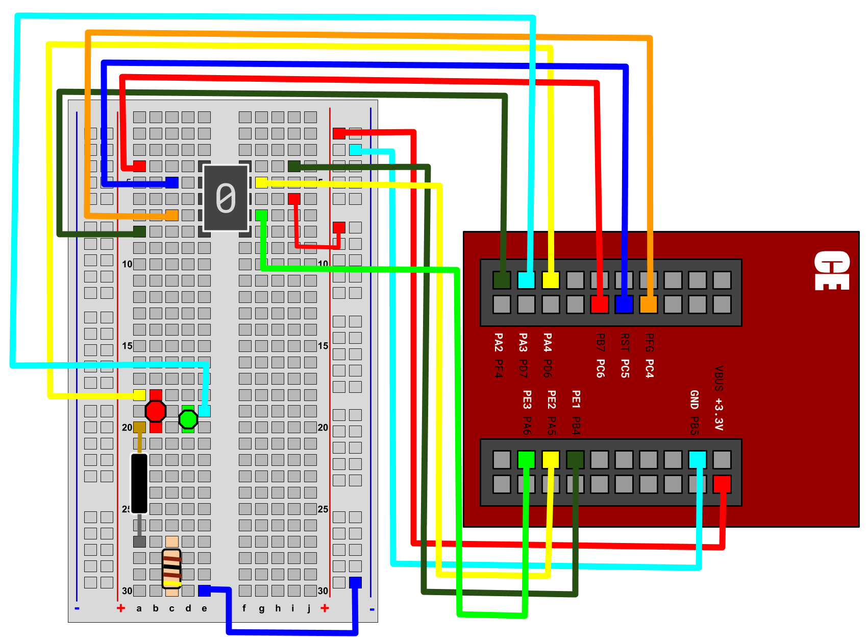
A daycare that was recently built suddenly realized they had nothing to entertain all of their tiny clients seven hours before their first day of business. With limited funds, they desperately looked to a group of bright students to develop a quick and simple solution to their problems. And what did this group of six come up with? ImPress the Button! A button pressing game that teaches young minds how to count. The game is simple: bright eyes look to a 7 segment LED display for a randomly generated number, then small fingers press a button a number of times. If they counted right, after tilting the device, a green light will illuminate their exciting faces. If they are wrong, a red light will shine instead and they can try again. Pressing the button again after getting it right will restart the game with a new number and the wonderful cycle continues!
Alexis Nicolas - atn44
Daniel Joshua - duj1
Joseph Gioia - jeg4
Peter Riera - pdr4
Surina Livingston - sll10
Venus Alemanji - va23
#include "helpers.h"
#include <time.h>
#include <stdlib.h>

// current_number is the number of times the player should hit the button
int current_number = 0;

void change_segment_display(int number){

    //Defines pins and ports the segments of the 7-segment display are connected to
    unsigned int volatile *pGPIODATAPortA = (unsigned int *) (PortA + GPIODATA);
    unsigned int volatile *pGPIODATAPortC = (unsigned int *) (PortC + GPIODATA);
    unsigned int volatile *pGPIODATAPortE = (unsigned int *) (PortE + GPIODATA);
    unsigned int volatile a = pin1;
    unsigned int volatile b = pin2;
    unsigned int volatile c = pin3;
    unsigned int volatile d = pin2;
    unsigned int volatile e = pin4;
    unsigned int volatile f = pin5;
    unsigned int volatile g = pin6;

    //clear display
    *pGPIODATAPortE |= a;
    *pGPIODATAPortE |= b;
    *pGPIODATAPortE |= c;
    *pGPIODATAPortA |= d;
    *pGPIODATAPortC |= e;
    *pGPIODATAPortC |= f;
    *pGPIODATAPortC |= g;

    //display number
    if(number == 1){
        *pGPIODATAPortE &= ~b;
        *pGPIODATAPortE &= ~c;
    }else if(number == 2){
        *pGPIODATAPortE &= ~a;
        *pGPIODATAPortE &= ~b;
        *pGPIODATAPortA &= ~d;
        *pGPIODATAPortC &= ~e;
        *pGPIODATAPortC &= ~g;
    }else if(number == 3){
        *pGPIODATAPortE &= ~a;
        *pGPIODATAPortE &= ~b;
        *pGPIODATAPortE &= ~c;
        *pGPIODATAPortA &= ~d;
        *pGPIODATAPortC &= ~g;
    }else if(number == 4){
        *pGPIODATAPortE &= ~b;
        *pGPIODATAPortE &= ~c;
        *pGPIODATAPortC &= ~f;
        *pGPIODATAPortC &= ~g;
    }else if(number == 5){
        *pGPIODATAPortE &= ~a;
        *pGPIODATAPortE &= ~c;
        *pGPIODATAPortA &= ~d;
        *pGPIODATAPortC &= ~f;
        *pGPIODATAPortC &= ~g;
    }else if(number == 6){
        *pGPIODATAPortE &= ~a;
        *pGPIODATAPortE &= ~c;
        *pGPIODATAPortA &= ~d;
        *pGPIODATAPortC &= ~e;
        *pGPIODATAPortC &= ~f;
        *pGPIODATAPortC &= ~g;
    }else if(number == 7){
        *pGPIODATAPortE &= ~a;
        *pGPIODATAPortE &= ~b;
        *pGPIODATAPortE &= ~c;
    }else if(number == 8){
        *pGPIODATAPortE &= ~a;
        *pGPIODATAPortE &= ~b;
        *pGPIODATAPortE &= ~c;
        *pGPIODATAPortA &= ~d;
        *pGPIODATAPortC &= ~e;
        *pGPIODATAPortC &= ~f;
        *pGPIODATAPortC &= ~g;
    }else if(number == 9){
        *pGPIODATAPortE &= ~a;
        *pGPIODATAPortE &= ~b;
        *pGPIODATAPortE &= ~c;
        *pGPIODATAPortC &= ~f;
        *pGPIODATAPortC &= ~g;
    }else if(number == 0){
        *pGPIODATAPortE &= ~a;
        *pGPIODATAPortE &= ~b;
        *pGPIODATAPortE &= ~c;
        *pGPIODATAPortA &= ~d;
        *pGPIODATAPortC &= ~e;
        *pGPIODATAPortC &= ~f;
    }

}

void button_press(){
    // Register to turn on and off the LEDs
    unsigned int volatile *pGPIODATA = (unsigned int *) (PortA + GPIODATA);

    // Turn off the leds
    *pGPIODATA &= ~pin3;
    *pGPIODATA &= ~pin4;

    // Based on what the current number is, change the number and turn on the correct LED
    if(current_number > 1){
        // Turn on red LED and decrement current_number by 1
        *pGPIODATA |= pin4;
        current_number--;
    }else if(current_number == 1){
        // Turn on green LED and decrement current_number by 1
        *pGPIODATA |= pin3;
        current_number--;
    }else{
        // Turn on red LED, set current_number to a new random number from 1-10 and display current_number
        *pGPIODATA |= pin4;
        current_number = rand() % 9 + 1;
        change_segment_display(current_number);
    }

    // Wait to prevent debounce
    int i=0;
    while(i<300000){
        i++;
    }

}

int main(void)
{
    // Set up ports that we need to use
    SetupDigitalGPIO(PortF, pin0, INPUT, NoINTERRUPT); // Button
    SetupDigitalGPIO(PortE, pin1, OUTPUT, NoINTERRUPT); // 7-Segment Display, segment A
    SetupDigitalGPIO(PortE, pin2, OUTPUT, NoINTERRUPT); // 7-Segment Display, segment B
    SetupDigitalGPIO(PortE, pin3, OUTPUT, NoINTERRUPT); // 7-Segment Display, segment C
    SetupDigitalGPIO(PortA, pin2, OUTPUT, NoINTERRUPT); // 7-Segment Display, segment D
    SetupDigitalGPIO(PortC, pin4, OUTPUT, NoINTERRUPT); // 7-Segment Display, segment A
    SetupDigitalGPIO(PortC, pin5, OUTPUT, NoINTERRUPT); // 7-Segment Display, segment A
    SetupDigitalGPIO(PortC, pin6, OUTPUT, NoINTERRUPT); // 7-Segment Display, segment A
    SetupDigitalGPIO(PortA, pin4, OUTPUT, NoINTERRUPT); // Red LED
    SetupDigitalGPIO(PortA, pin3, OUTPUT, NoINTERRUPT); // Green LED

    // Set priority
    NVIC_PRI7_R = (NVIC_PRI7_R&0xFF00FFFF)|0x00A00000; // priority 5

    //Enable
    //   For this register, each bit corresponds to a different interrupt
    //   that can be enabled.
    //   For interrupt 1, you'd need a 1 in bit position 1.
    NVIC_EN0_R |= 0x40000000;

    // Registers to turn on and off the LEDs and detect a button press
    unsigned int volatile *pGPIODATAPortF = (unsigned int *) (PortF + GPIODATA);
    unsigned int volatile *pGPIODATAPortA = (unsigned int *) (PortA + GPIODATA);

    // Start with red LED on because player hasn't won yet
    *pGPIODATAPortA |= pin4;

    // Set current_number to a new random number from 1-10 and display current_number
    current_number = rand() % 9 + 1;
    change_segment_display(current_number);

    // Define the current position of the button as off
    int switch_position = *pGPIODATAPortF & pin0;
    int prev_position = switch_position;
    int on = 0;
    while (1)
    {
        // Find the current position of the button
        switch_position = *pGPIODATAPortF & pin0;

        // If the position of the button has changed to be on, run the button_press function
        if(switch_position!=prev_position){
            if(on == 0){
                on = 1;
                button_press();
            }else{
                on = 0;
            }
        }

        // Define the previous position of the button to be what the current position is now
        prev_position = switch_position;
    }
}
/*
 * helpers.h
 *
 *  Created on: Mar 15, 2018
 *      Author: Chance Tarver
 */

#ifndef HELPERS_H_
#define HELPERS_H_


// Base addresses of each port
#define PortA       0x40004000
#define PortB       0x40058000
#define PortC       0x40006000
#define PortD       0x40007000
#define PortE       0x40024000
#define PortF       0x40025000

//  General-Purpose Input/Output Run Mode Clock Gating Control. Each bit corresponds to a Port.
#define RCGCGPIO    0x400FE608
#define ClocksA     0x01
#define ClocksB     0x02
#define ClocksC     0x04
#define ClocksD     0x08
#define ClocksE     0x10
#define ClocksF     0x20

// Define the bitmask for each pin
#define pin0     0x01
#define pin1     0x02
#define pin2     0x04
#define pin3     0x08
#define pin4     0x10
#define pin5     0x20
#define pin6     0x40

//Other defines for code readability
#define OUTPUT  1
#define INPUT   0
#define INTERRUPT    1
#define NoINTERRUPT  0

// Offsets corresponding to registers we may need to configure
#define GPIODATA    0x3FC   // pg662 : GPIO Data // Why isn't this 0x000
#define GPIODIR     0x400   // pg663 : GPIO Direction
#define GPIOIS      0x404   // pg664 : GPIO Interrupt Sense
#define GPIOIBE     0x408   // pg665 : GPIO Interrupt Both Edges
#define GPIOIEV     0x40C   // pg666 : GPIO Interrupt Event     -   0: falling edge or Low level is trigger.    1: rising edge or High level is trigger
#define GPIOIM      0x410   // pg667 : GPIO Interrupt Mask      -   0: the pin is masked.                       1: the interrupt is sent to the controller
#define GPIOICR     0x41C   // pg670 : GPIO Interrupt Clear     -   0: no affect                                1: the corresponding interrupt is cleared
#define GPIOAFSEL   0x420   // pg671 : GPIO Alternative Function Select - 0: pin functions as GPIO              1: Function as something else depending on port
#define GPIOPUR     0x510   // pg677 : GPIO Pull-Up Select      -   0: turn off pull up resistor                1: turn on pull up for corresponding pin
#define GPIOPDR     0x514   // pg679 : GPIO Pull-Down Select    -   0: turn off pull down resistor              1: turn on pull down for corresponding pin
#define GPIODEN     0x51C   // pg682 : GPIO Digital Enable      -   0: disable digital functions                1: enable pin's digital functions
#define GPIOLOCK    0x520   // pg684 : GPIO Lock. A write of the value 0x4C4F.434B unlocks the GPIO Commit (GPIOCR) register for write access.
#define GPIOKEY     0x4C4F434B // pg684. Special key for the GPIOLOCK register
#define GPIOCR      0x524   // pg685 : GPIO Commit              -   0: Corresponding GPIOAFSEL, GPIOPUR, GPIOPDR, or GPIODEN bits cannot be written. 1: They can

#define NVIC_EN0_R              (*((volatile unsigned long *)0xE000E100))  // pg142 IRQ 0 to 31 Set Enable Register

#define NVIC_PRI0_R             (*((volatile unsigned long *)0xE000E41C))  // pg152 IRQ 0 to 3 Priority Register
#define NVIC_PRI7_R             (*((volatile unsigned long *)0xE000E41C))  // pg152 IRQ 28 to 31 Priority Register  pg 104 has interrupt assignments. GPIO Port F is Interrupt #30. Bits 23:21

void WaitForInterrupt(void);  // low power mode

void SetupDigitalGPIO(unsigned int port, unsigned int pinMask, int direction,
                        int useInterrupts)
{
    /*Function for setting up a digital GPIO Pin

     This function will do all the register configs for a give port and pin.

     Examples
     -------
     SetupOnDigitalGPIO(PortF, pin3, INPUT, INTERRUPT) // Set up an input with interrupts on PF3.
     SetupOnDigitalGPIO(PortE, pin4, OUTPUT, NoINTERRUPT) // Set up an output with no interrupts on PE4.
     Notes
     -----
     We assume a pullup resistor.
     We also assume an edge based trigger.
     It is best the header with the #defines for each port and pin are included.

     Inputs
     ------
     (*((volatile unsigned long *) port  - Base address of the port being used.
     (*((volatile unsigned long *) pin   - Bit mask of the pin being used
     int direction - Boolean flag for direction of the pin. 1 = Output. 0 = input
     int UseInterrupts - Boolean flag to use interrupts. 1 = use them. 0 = don't
     */

    //Define the generic pointers
    unsigned int volatile *pRCGCGPIO = (unsigned int *) RCGCGPIO;
    unsigned int volatile *pGPIOLOCK = (unsigned int *) (port + GPIOLOCK);
    unsigned int volatile *pGPIOCR = (unsigned int *) (port + GPIOCR);
    unsigned int volatile *pGPIODIR = (unsigned int *) (port + GPIODIR);
    unsigned int volatile *pGPIOAFSEL = (unsigned int *) (port + GPIOAFSEL);
    unsigned int volatile *pGPIOPUR = (unsigned int *) (port + GPIOPUR);
    unsigned int volatile *pGPIODEN = (unsigned int *) (port + GPIODEN);
    unsigned int volatile *pGPIODATA = (unsigned int *) (port + GPIODATA);

    // Define the pointers for interrupt configuration
    unsigned int volatile *pGPIOIS = (unsigned int *) (port + GPIOIS);
    unsigned int volatile *pGPIOIBE = (unsigned int *) (port + GPIOIBE);
    unsigned int volatile *pGPIOIEV = (unsigned int *) (port + GPIOIEV);
    unsigned int volatile *pGPIOIM = (unsigned int *) (port + GPIOIM);
    unsigned int volatile *pGPIOICR = (unsigned int *) (port + GPIOICR);

    // activate the clocks for the port
    int clocks;
    switch ((int) port)
    {
    case PortA:
        clocks = ClocksA;
        break;
    case PortB:
        clocks = ClocksB;
        break;
    case PortC:
        clocks = ClocksC;
        break;
    case PortD:
        clocks = ClocksD;
        break;
    case PortE:
        clocks = ClocksE;
        break;
    case PortF:
        clocks = ClocksF;
        break;
    default:
        clocks = ClocksF; //ERROR. TODO: Add an exception to handle this. Send to Error ISR or something
    }

    *pRCGCGPIO |= clocks;
    while ((*pRCGCGPIO & clocks) == 0)
        ;

    *pGPIOLOCK = GPIOKEY;
    *pGPIOCR |= pinMask;
    if (direction == 0)
    {
        *pGPIODIR &= ~pinMask;
        *pGPIOPUR |= pinMask;
    }
    else if (direction == 1)
    {
        *pGPIODIR |= pinMask;
    }
    else
    {
        *pGPIODIR |= pinMask; // TODO. Addd an exception to handle this.
    }

    *pGPIOAFSEL &= ~pinMask;
    *pGPIODEN |= pinMask;

    if (useInterrupts)
    {
        *pGPIOIS &= ~pinMask;  // Edge-sensitive (default setting)
        *pGPIOIBE &= ~pinMask;  // Not both edges (default setting)
        *pGPIOIEV &= ~pinMask;  // Falling edge event (default setting)
        *pGPIOICR |= pinMask;   // clear flag
        *pGPIOIM |= pinMask;   // enable interrupt. Unmask it
    }
}


void WaitForInterrupt(void)
{
    __asm ("    WFI\n"
            "    BX     LR\n");
}


#endif /* HELPERS_H_ */


Comments
Please log in or sign up to comment.