Hi, this project is about how to use the analog stuff of PsoC Analog Coprocessor to measure a automobile engine speed using the battery voltage, the main goal of this is to give a alternative of sense the camshaft speed using anoter sensor insted the actual magnetic pickup.
The good news, is the PSoC Analog Coprocessor has all the necessary analog components to prepare signal to be captured to it analog to digital converter and perform right calculations.
How it works:
The theory behind to measure is quite simple, during otto cycle compression and expansion cycles (ignition hits to air/gasoline mixture), the piston will accelerate rapidily, which is compensated by its mechanic construction, but this pertubartion is feel by the alternator which creates a high frequency component on voltage line, since this perturbation is periodic, the alternate component of battery voltage (tons of milivolts) will has a high frequency component which is proportional of the engine speed.
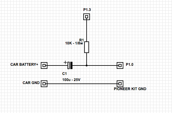
So, the first task is to decouple the DC voltage from battery before it hits to the psoc, this is made by a DC blocking capacitor, the alternate voltage is biased by the reference voltage generated from P1.3 of the pioneer kit, then the resulting signal is directly fed to the P1.0 of pioneer kit (yes, this means you can built it with few external components), then the signal will pass by a amplify stage then a band-pass filtering, which has two functions, first it removes the low frequency alternate components and acts as a anti-aliasing filtering to the A/D section.
The samples captured are fed into a ping-pong buffer managed by the psoc DMA component. The firmware receive a Interrupt request with a new block of samples and perform a Fast Fourier Transform on the blocks then finds the frequency which has the major valued magnitude, take it and apply a scale factor to obtain the RPM value and it sent by the UART with 8N1 setting at 115200 bps.
The schematic made in psoc creator is shown below:
How build it:
The build process is simple, firstly you need to prepare the wires, so connect the cables from you car to board (or a signal generator for tests) using the following schematic:
Build the firmware supplied, you can test different configurations of converter factors of RPM, in engine_afe.c you will find two constants, ENGINE_BASE_FREQ, and ENGINE_SCALE_FACTOR, modify then on your own purposes to different car models (different noof cylinders will need change on these values). then open a terminal with your favorite tool (with pioneer kit connected) with 115200 bps and 8N1, as a example in my MAC the result you will see below will be similar on your PC / Notebook:
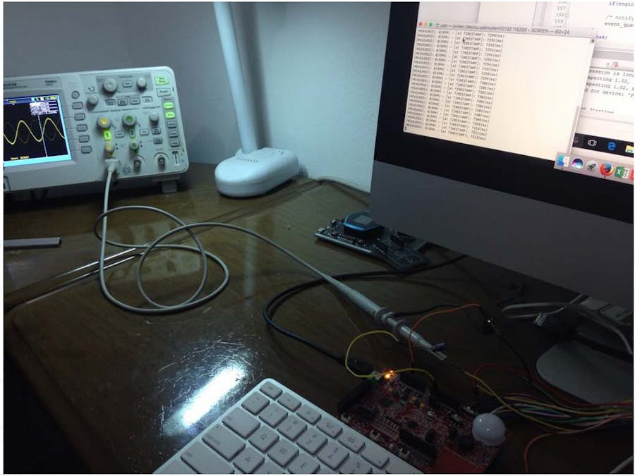
Here are some screeshots during prototype phase, I used my signal generator to simulate te noisy signal, the the shown in osciloscope is the filtered and amplified signal before hits the A/D converter:
Bad things ocurred:
After the development I will finally connect on car, but I accidentally dropped the board into battery points of my car...the result psoc burned out, with no time left to buy a another board I unfortunately will hold this project until the new board arrives.
But, you can test (taking careful and using a long cable) yourself and tune to your own purposes. also this project can be reused as analog conditioning and signal processing to another bands, since the analog front-end is ready and tested, the ADC an DMA is working all you need is to add on KDMA_EVENT_READY section your own digital signal processing in place (or reuse) the fix_fft algorithm. So the board was damaged but the good news you can take this design and modify to your own.
I hope the project and story be useful to any one which wants to start to build your own digital signal processing engine using this powerful analog coprocessor :)
If you want some support during build, please contact me via profile I will be pleased to help you :D


Comments
Please log in or sign up to comment.