MPU 6050 is a sensor with 3-axis Gyroscope and 3-axis Accelerometer sensor. The sensor is designed with motion detection capabilities with inbuilt motion and fall detection algorithms. There is also possibility to self-test the sensor, and connect other i2c sensor like magnetometer to get the heading information on the auxiliary i2c bus (Aux-SDA, Aux-SCL).
In this project description, I will tell you what make it interesting to create a Grove compatible module for MPU6050 sensor and what are the steps I followed.
I will go with the following flow.
- The MPU6050 sensor and features
- The Grove factor design using Seeed studio's fusion services
- The Arduino compatible wire library
The InvenSense MPU6050 is a motion tracking device. As per the defination we can also call it IMU(Inertial measurement unit) sensor. It is a sensor with accelerometer and gyroscope which can detect linear and angular motion in (+/-)(X, Y, Z) axis respectively.
It has an accelerometer which can detect linear acceleration in the range of +/-(2g, 4g, 8g, 16g) and gyroscope which can detect angular motion in the range +/-(250*/s, 500*/s, 1000*/s, 2000*/s).
The sensor comes with motion detection and fall detection algorithms that can trigger interrupt for sensing from the host microcontroller.
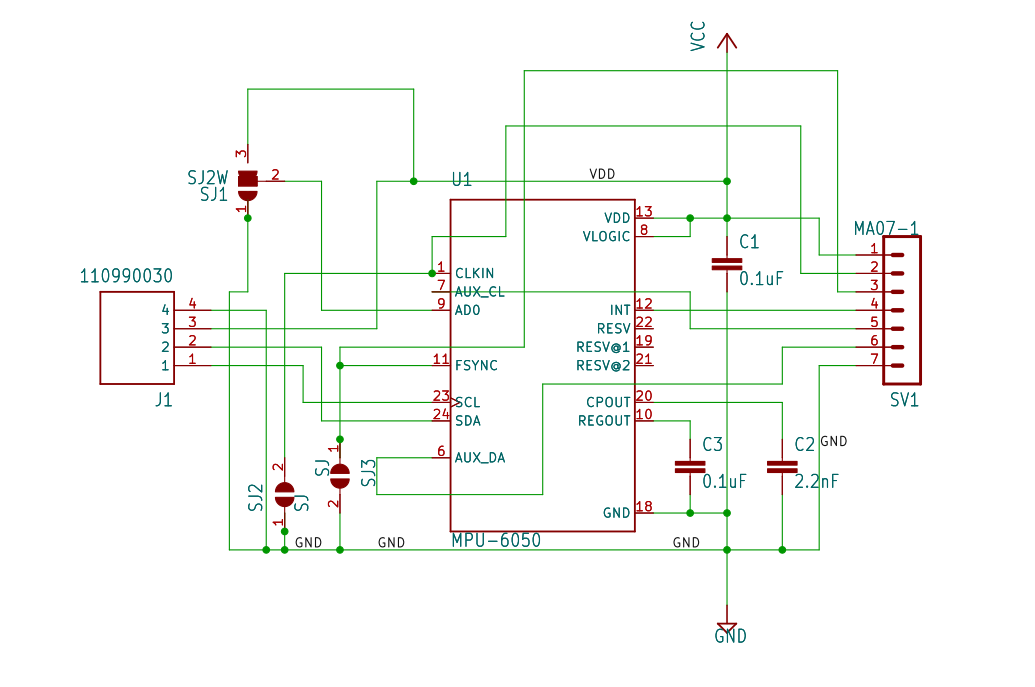
From the above pin diagram it is clear that the sensor comes with the i2c interface pins like scl and sda. It also has aux_da and aux_cl for connecting external i2c sensors and fetching their data into the registers for creating sensor fusion or algorithms for motion tracking.
The INT pin is used for creating interrupt for the device. Other pins such as FSYNC can also be used as interrupt if more than one interrupt is enabled.
Seeed Studio's Grove designSeeed has Grove system which supports nearly 400 different sensors. This grove specification can be used to create sensor boards with interfaces such as i2c and uart.
Seeed currently has a co-invent campaign where designers can design a grove sensor module for free and chance to win over $300. It can be quite useful of one does not find a grove module that they like or have already knowledge, to create one. I already had worked on MPU6050 and had created a library for the same hence, I thought this could be a great opportunity for me to introduce this grove module.
For this project I chose the 20x40 SMD design out of Grove specification.
The PCB can be ordered on seeed's fusion PCBA service with different parameters. For this project a two-layer PCB design was sufficient.
In the above figure, there are some default jumpers(SJ2, SJ1, SJ3 respectively from the left) which need to be soldered properly in order for the sensor to operate correctly. These jumpers are there to select the i2c address, slave configuration on i2c bus and clock synchronisation of the device in case an external device is connected. Both the jumpers pads of (SJ2, SJ3) need to be soldered and the middle pad of SJ1 needs to be soldered with bottom pad(to the 7-pin header side). With this Grove-MPU6050 is ready to function as an i2c device to the host microcontroller.
I have created a library for MPU6050 and published it online on Gitlab. Any arduino compatible board can be used to interface with the sensor.
Download and install the.zip version of the library in arduino.
Alternatively, the library is also there is the library manager menu of Arduino. It can be installed by typing MPU6050_IND in the search options.
Open the examples from the Files -> examples -> simple_accelerometer example and click the upload button. After the upload is successful open the serial monitor to view the readings of the sensor data. You will see the Accelerometer and Gyroscope data on the serial monitor window.
There is also one more interesting example, which I would like to mention is how to create interrupt when specified level of fall detection threshold is crossed. In the example output Led can be used to have visual indication of fall.
The second example exactly demonstrates this behavior. For interrupt to work on Arduino Uno one has to select the right interrupt pins which are pin no. 2 & 3. Only these pins can detect the signals from external signals and create interrupt. So, choose for your board accordingly.
The following is the example code for ISR(interrupt service routine) in Arduino which will turn on the LED.
void interrupt_service_routine()
{
  Serial.println("Fall..");
  falldetection = true;
  digitalWrite(LED_PIN, HIGH);
}
After the LED is turned on the counter will count for sometime, and will run delay() functions to keep led on. Once the count reached to count==10, the interrupt will be cleared and LED will turn off again, returning to normal state.!!
void loop() {
  // put your main code here, to run repeatedly:
  delay(500);

  if(falldetection == true)
  {
    count += 1;
    if(count==10)
    {
      digitalWrite(LED_PIN, LOW);
      falldetection = false;
      imu.readbyte(INT_STATUS);
      count=0;
    }
    Serial.println("Fall detected....LED is Turned ON");
    delay(100);
  }
  Serial.print("Count ");
  Serial.println(count);

}
The LED on pin 13 of Arduino is turned on when the fall is detected for around 10 seconds.
After learning from the previous design I have modified the original design with improvements. Such as reducing the components not required and having better design. Also making the design both 3.3v and 5v capable by using BSS138 level converter switches for i2c and other data lines.
Which will make Grove-MPU6050 robust against voltage changes. It still will support interfacing auxiliary i2c sensors and interrupt pins.
Thanks to Seeed for their support.


_LWNORVejBN.png?auto=compress%2Cformat&w=48&h=48&fit=fill&bg=ffffff)


Comments
Please log in or sign up to comment.