


Hardware components | ||||||
_ztBMuBhMHo.jpg?auto=compress%2Cformat&w=48&h=48&fit=fill&bg=ffffff) |
| × | 1 | |||
 |
| × | 1 | |||
 |
| × | 6 | |||
| × | 1 | ||||
 |
| × | 6 | |||
Software apps and online services | ||||||
 |
| |||||
To be truthful, this project started on a whim. The question was: how can a MC74HC14A Hex Schmitt-Trigger Inverter be combined with an Arduino to do something? This is the result. Of course, the result is purely frivolous and has no real application other than it looks cool.
Here are the major components
- Arduino Uno
- MC74HC14A Hex Schmitt-Trigger Inverter
- 6 x 220 Ohm Resistor
- 6 x Colored LED’s
MC74HC14A Hex Schmitt-Trigger Inverter
The Schmitt trigger inverter is used to output square waves of the correct voltage to power an LED array. By cascading the gates, alternating square waves can be produced. A Schmitt trigger circuit includes hysteresis which ensures precise transitions from HIGH to LOW and from LOW to HIGH in a digital signal.
Link to a data sheet
https://www.mouser.com/datasheet/2/308/MC74HC14A-D-601265.pdf
If you are interested in the theory behind a Schmitt trigger inverter, there are numerous articles on the internet describing their operation.
Dimming and lighting LED's with PWMThis project uses the PWM capabilty of the Arduino UNO to alternatively light up and dim down an LED. A approximate picture of PWM with a brief explanation is shown below:
PWM relies on the UNO outputting a square wave with a variable duty cycle. At low duty cycle, the outputted square wave is of short duration and the average voltage of the resulting wave is low because most of the time 0V is been output. At high duty cycles, the outputted square wave is of long duration and the average voltage of the resulting wave is high because most of the time it is near 5V.
Refer to https://docs.arduino.cc/learn/microcontrollers/analog-outputfor a far better explanation.
Because the output frequency is high, an LED reacts to the average voltage only. Therefore – low duty cycle = dim LED, high duty cycle = bright LED.
The relevant Arduino instructions are:
pinMode(ledPin, OUTPUT);
analogWrite(ledPin, fadeValue);
fadeValue is an integer between 0 and 255. A fadeValue of 0 represents no output voltage and a value of 255 represents a steady 5V output.
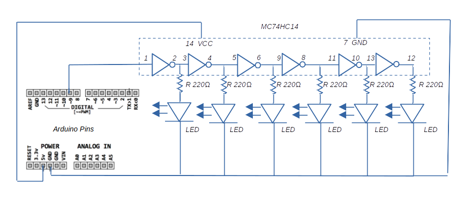
The CircuitHere is a schematic of the circuit used in this project:
Pin 9 is used as a PWM output.
The output of each Schmitt trigger gate is inverted from its input. In the circuit, the six Schmitt triggers are connected in series. As a result of this, LED 1 sees a PWM signal which is the inverse of the signal output by pin 9. LED2 sees a signal identical to that output by Pin 9 (double inversion = original), LED3 sees an inverse, LED4 sees an identical and so on.
Therefore for max output voltage on pin 9, LED2, LED4 and LED6 will be brightly lit and LED1, LED3 and LED5 will be off. Min output from pin 9 will result in the opposite.
In the Arduino IDE, there is a simple example of how to brighten and fade an LED. See File > Examples > 01.Basics > Fade
This example uses a linear voltage ramp up; for each time increment the voltage increment is proportional. The aesthetic problem with this method is that the LED brightness does not increase and decrease in a linear manner. Rather, the LED brightness initially increases quickly and then tends to saturate to max brightness after about halfway along the voltage ramp up.
If you refer to the graph below, the voltage is following the linear y=x graph (orange), but the LED brightness is following something like the yellow curve.
To get the LED brightness to ramp up in a more linear fashion, the applied voltage must follow a ramp up something like the Compensated Voltage (Blue) shown in the graph.
So how is this achieved? The following equation allows for a compensated voltage:
- y is the output voltage between 0 and 1
- m is a constant. As m increases, the amount of deviation away from the linear curve increases.
- X is a value between 0 and 1
- The 255 multiplier is required to produce a result that can be used in the analogWrite(ledPin, fadeValue); Arduino function. This requires a value between 0 and 255.
Armed with this equation, we can code up a compensatedvoltage output that gives a better LED brightness increase and decrease.
Code Explanation- In the variable initialization section, floatmValue = 6.0; sets up the constant m. it can be changed to achieve differing LED dimming and brightening effects.
- In the setup loop, the Arduino pin that is connected to the initial input of the Hex Schmitt trigger is defined.
- The main loop consists of two for loops, one for increasing from 0 to max brightness and one for decreasing from max to no brightness. The loops count from 0 to 1 in increments of 0.05.
- The compensation function is applied to the loop counter and multiplied by 255 to get a value.
- This value is converted to an integer and used to output a voltage at the analog pin which connects to the circuit.
Once the code is uploaded, the the LED array will begin brightening and dimming. Enjoy the show.


Comments
Please log in or sign up to comment.