Buying this board is easy. For about $12 to $17, it can be found on many sites such as Amazon, eBay, and AliExpress. One click shopping.
Using it is not so easy, multiple internet searches produced no comprehensive documentation, other than brief specifications associated with the postings. But do not despair, this project shows how the development board can be programmed and used.
SpecificationsHere are the specifications taken from the eBay listing.
ESP8266 clock module, using ESP-12F module with ESP8266 as the main control; onboard a 0.96 inch OLED, clock chip, five-way button, single-cell 18650 lithium battery charging chip; the battery can be charged through the microUSB interface. Users can develop a different WiFi clocks using this board.
Board features:
- 0.96 inch OLED to display time and other data
- Clock can be calibrated via WiFi
- Powered by a 18650 lithium battery allowing portability
- Micro USB port will charge the 18650 lithium battery, board includes a charging indicator
- Access to a subset of the ESP8266 pins that can be interfaced to other hardware
- Micro USB automatic programming function
- Five-way button connected to five pins.
After purchasing the board, a detailed examination of the components (via magnifying glass) showed the following included IC’s:
- 18650 lithium battery holder (on underside of board)
- TP5400 lithium-ion charge/boost chip. Used for charging the 18650 battery
- CH340 USB to Serial interface
- CJT1117B low dropout linear 3.3V regulator
- ESP-12F module including the ESP8266 WiFi chip
- 8563 Real Time Clock (RTC) chip
- CR1220 Li Battery holder
- 128 x 64 OLED display driven by SSD1306
- Five way Button connected to the ESP8266
Which is a lot of stuff on a single board.
If you connect a USB cable to the Micro USB input, and switch the On/Off switch to right hand position (looking from above), the board boots up and displays the time and date with associated Chinese characters. Multiple searches have not produced the source code that gives this result.
So – lets figure it out.
Program ESP8266 from Arduino IDEBefore programming the ESP8266, you have to ensure that the Arduino IDE you are using is configured to do this type of programming. There are numerous articles on the Internet explaining how to do this. A search of “program ESP8266 from Arduino IDE” will provide many results.
Here are a few links:
https://www.instructables.com/Setting-Up-the-Arduino-IDE-to-Program-ESP8266/
https://randomnerdtutorials.com/how-to-install-esp8266-board-arduino-ide/
The basic steps are as follows:
- In File → Preferences, add a url to the Additional Boards Manager: http://arduino.esp8266.com/stable/package_esp8266com_index.json
- Under Tools → Boards → Boards Manager, Search for ESP8266 and install latest version of “ESP8266 by ESP8266 Community” (In the Arduino IDE Ver 2.0, the boards manager is located on the left hand side of the screen)
- Once this is done, you should have an option under Tools→ Board for a ESP8266 Boards. Choose Generic ESP8266 Module.
In Arduino IDE V2.0, you should see a screen that looks as follows:
Because this specific board uses a CH340 USB to Serial Interface, special drivers are required. Search for information on how to install this if required.
ESP8266 BlinkEverybody starts off with the Blink program. So let us not upset tradition.
Warning – this step will wipe out the pre-loaded program that the board comes with. If this is to drastic, stop here.
The built in LED is connected to GPIO2
If you are ambitious, connect a 220 Ohm resistor and LED between the pin labeled IO2 and GND.
Normally, the ESP8266 requires a separate configuration to program. GPIO0 has to be grounded while programming. Once the program has been flashed, GPIO0 is then returned to 5V and the program executes.
In the case of this development board, that process is transparent to the user, and the board can be programmed just like an Arduino.
So, to get the blink to work follow following steps:
- Connect your computer to the Micro USB port on the board. Open “BlinkESP8266.ino” in Arduino IDE
- Click the upload button and wait for the message – “Hard resetting via RTS pin….”
- The ESP8266 will automatically reset
- LED’s will start blinking – success!
- Also, the word “Test” will print out on the Serial Monitor
That was easy
Five Way ButtonThe five way button is connected to the ESP8266 inputs as shown in the diagram (button orientated as shown in the picture)
To use the button, your program must include this command in setup
pinMode(pin, INPUT_PULLUP);
The state of the button can be read using
digitalRead(pin);
This returns High or Low
Also, be careful of GPIO0 and GPIO1 – these are used for Serial communication (Tx and Rx);
PCF8563 Real Time ClockThe PCF8563 is a CMOS Real-Time Clock (RTC) and calendar. Battery back up will ensure that it does not go out of calibration, even if main power is removed.
All addresses and data are transferred serially via a two-line bidirectional I2C bus. Refer to the datasheet for more details.
The development board includes a PCF8563 IC and a CR1220 backup battery. This battery will ensure that the PCF8563 will retain time even if main power is removed from the board.
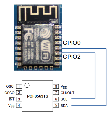
By process of elimination and measuring resistance on the board it was discovered that the I2C bus from the PCF8563 is connected to GPIO0 and GPIO2 on the ESP8266 (pins 17 and 18). Some more experimentation shows GPIO0 is SDA and GPIO2 is SCL.
To demonstrate the PCF8563, we will use the RTClib library from Adafruit. Install this library in the Arduino IDE.
The code used here is based on the example for the PCF8563 included with the library (with minor additions). The code uses the underlying Wire library normally included with the Arduino IDE. This library handles the low level I2C communications.
By default, the ESP8266 uses GPIO4 and GPIO5 for I2C communication, and unless this is otherwise defined, the Wire library will use these outputs/inputs. This is not the case for our configuration, so needs to be defined in the code.
Wire library contains a undocumented function:
Wire.begin(SDA,SCL);
Which allows the code to define which inputs/outputs are dedicated to I2C communication. So, in this case we must include following in Setup:
Wire.begin(0,2);
To demonstrate working of the PFC8563 use the following steps:
- Make sure RTClib is installed
- Compile and upload the code “RTC8563Demo.ino” to the ESP8266. See code for explanation of operation
- Once the ESP8266 resets, the Serial Monitor should show date and time printouts every 8 seconds
- The date and time displayed is derived from the date and time current on your computer at the time of program compilation
The development board includes a 128 x 64 OLED display.
An OLED display can be accessed via I2C or SPI protocol.
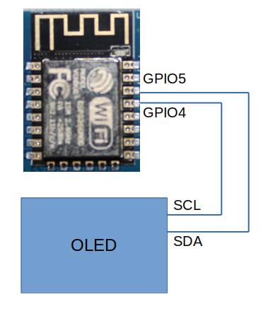
By process of elimination and measuring resistance on the board it was discovered that the OLED uses an I2C bus connected to GPIO4 and GPIO5 on the ESP8266 (pins 20 and 19). Some more experimentation shows GPIO5 is SDA and GPIO4 is SCL. Which is inverted from the default (for some obscure reason).
To demonstrate the working of the OLED, we will use the Adafruit_GFX and Adafruit_SSD1306 libraries from Adafruit. Install these libraries in the Arduino IDE.
Because the SCL and SDA lines are inverted from the default, the following command is required in setup:
Wire.begin(5,4);
To demonstrate working of the OLED use the following steps:
- Make sure Adafruit_GFX and Adafruit_SSD1306 libraries are installed
- Compile and upload the code “OLEDDemonstration” to the ESP8266. See code for explanation of operation
- Once the ESP8266 resets, the OLED will display some messages.
To demonstrate working of the ESP8266 WiFi capabilities, use this example.
- Compile and upload the code “ESPAccessPoint.ino”
- Open the Serial Monitor and ensure that the access point has been started. Check the IP address allocated to the AccessPoint.
- Using any device with WiFi capabilities (Smart Phone, Tablet, Laptop etc.) connect to the WiFi network “ESP8266Network” with password “1234567890”
- Open a browser on the connected device. Type in the IP address into address bar from previous step
- You should get a message “You are connected” in the browser.
Easy
Final DemonstrationLet us put all this together for a final demonstration of the development board.
Before getting into the demonstration, a brief description of how to retrieve accurate time from the internet. The Network Time Protocol (NTP) project is an open source collaborative effort that maintains a website (www.ntp.org) that provides accurate time to any internet connected device querying a pool of servers. If more details are required, visit the website.
In this project, the ESP8266 is connected to the internet, it can then send a query (using the UDP protocol) and obtain the accurate time. This timestamp is provided by the website is so called “UNIX time” or the number of seconds since Jan 01 1970. (UTC).
High level flow chart of the final program
For this demonstration, following libraries required:
- Adafruit_GFX
- Adafruit_SSD1306
- RTClib
- ESP8266WiFi
- EasyNTPClient
If all the proceeding steps in this project have been implemented, the only additional library that needs to be installed is EasyNTPClient. This retrieves the time from www.ntp.org and provides routines to convert from UNIX time to current time.
To run the demonstration use following steps:
- Install library EasyNTPClient
- Download the code “ESP8266FinalProject.ino”
- Edit the code on lines 13 and 14 to insert wireless network and password
- Edit the declaration for EasyNTPClient to specifiy correct timezone. This number is the number of seconds timezone is ahead or behind UTC
- Compile and upload the code to the development board
- Date and Time will be displayed on the OLED
Good Luck


Comments
Please log in or sign up to comment.