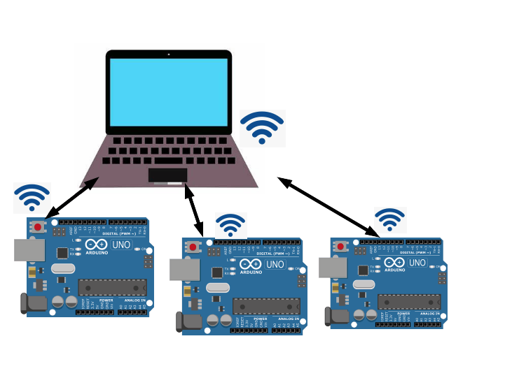
In a previous project, I connected an Arduino and ESP13 WiFi shield combination to a laptop over a WiFi network and was able to pass commands back and forth over the network.
https://www.hackster.io/umpheki/control-your-arduino-from-your-laptop-via-wifi-with-esp13-346702
The next step was to see if it was possible to connect multiple Arduino/ESP13 combinations to a laptop over a WiFi network and capture data from all of the Arduinos into a single file. This would be a simple local IOT setup that could be extended to many different applications.
At a high level, the shield functions as a serial transmitter and receiver across a WiFi network. Once configured, the Arduino sends and receives information using the Serial.print() and Serial.readstring() functions to communicate with a remote host over a wireless network.
See my previous project for a more complete description of the ESP13 shield. It can be purchased on ebay or other sites for a few dollars.
This project will show how a python program running on a laptop (or workstation) can connect to multiple Arduinos fitted with the ESP13 shield. These combinations are connected to a DHT22 temperature/humidity sensor and sends readings to the python program every 15 seconds. The results are recorded in a CSV file on the laptop and can be analyzed over a given time period. High level steps as follows:
- Fit shield to Arduinos and connect DHT22 sensor
- Configure ESP13 module
- Run Python program on laptop
- Connect ESP13 to the Python program
- Temperature and Humidity readings from the Arduinos are logged
- Once capture period is over, results can be analyzed
Sockets are used in all networks to communicate data between devices. Although you may not be aware, every time you use a browser, a socket is buried in the stack facilitating that data transfer. They exist at the Session Layer of the OSI network model and most programming languages have libraries that allow for the creation and maintenance of sockets. The ESP13 WiFi shield connects via a socket and the computer or device communicating with the shield needs to create and maintain a socket for this interchange.
I used a Python 3 program and the associated socket library to facilitate communication between the ESP13 and the laptop. It is not the intention of this tutorial to provide instruction on socket programming. There are many resources on the internet that explain how they work and how they can be used in programs.
https://realpython.com/python-sockets/
https://docs.python.org/3/howto/sockets.html
However, it is worth noting that because a socket exists at the Session Layer of the OSI model, the program has to do all the functions above that level.
A Note on Python Multi ThreadingPython multi threading allows you to have different parts of your program run concurrently in different threads and can simplify program design. In this project, seperate threads were used to handle communication with each individual Arduino. This allows flexibility on how many Arduinos are connected and simplifies the program design.
Specifically, the threading module allows two advantages for this project:
- Certain of the socket calls are “blocking”, meaning that they suspend program execution while waiting for an event. By putting these calls into their own thread, the rest of the program can carry on executing without been blocked
- The threading module includes a lock function which allows for only one device to access the single logging file and prevents race conditions.
Here are a few resources on the internet that give very good explanations of multi threading in python:
https://realpython.com/intro-to-python-threading/
https://docs.python.org/3/library/threading.html
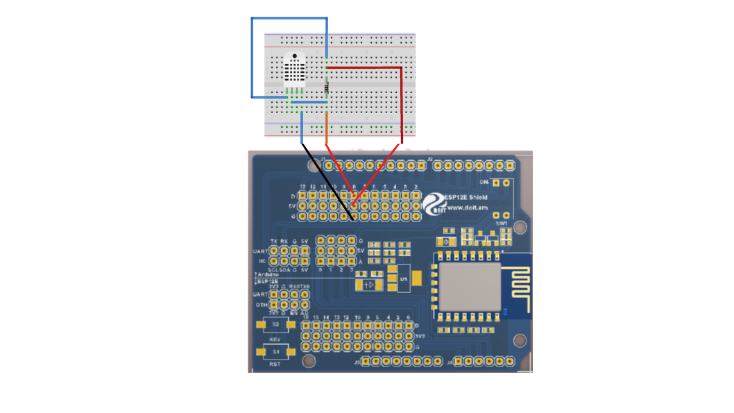
Arduino ConfigurationFit the shield to the Arduino as shown in the first photograph. Then go ahead and connect the DHT22 sensor to the shield as shown. If in doubt, there are plenty of tutorials available on how to use the DHT22.
Included is a 10K pull up resistor for the data pin of the DHT22.
Set the dip switch (1 and 2) to ‘OFF’
Download the sketch included with this tutorial to the Arduino. Having the switches set to off disconnects the Arduino from the ESP13 shield and allows for the sketch upload to the Arduino.
Because we are connecting multiple Arduinos to a single python program, the specific Arduino must have a unique identifier. The sketch included with this project identifies “Arduino1” in the program. Before uploading to a second Arduino, edit the program and change “Arduino1” to “Arduino2” (approx line 46 of the code). Save it with a new name.
The Arduino program uses the standard DHT library. Pin 6 is designated as the data pin.
ESP13 Module ConfigurationThe ESP13 Module is configured via a webpage served from the ESP3866. Use the following steps:
Before starting, connect the laptop or computer to the wireless network you will be using to communicate with your Arduino. Then establish the IP address of your computer or laptop on this network (ipconfig in windows for example) and record this.
- Before starting, connect the laptop or computer to the wireless network you will be using to communicate with your Arduino. Then establish the IP address of your computer or laptop on this network (ipconfig in windows for example) and record this.
- Power Up the Arduino - this will provide power to the ESP13 shield.
- Disconnect your laptop or computer from the network used in Step1. Scan for available WiFi networks and you should see a network called DoitWiFi_Config. Connect to this network. It should have no password. If a password is required it will be 12345678.
- Open a browser and use the address http://192.168.4.1. This will bring up the ESP13 configuration page
- Set Baud rate to 115200
- Use the Refresh button to scan for available WiFi networks and select from the AP List drop down the WiFi network you intend to use for communication. The grey boxes will fill automatically.
- Enter the network password
- Under NetWork Setting pick Client and TCP. Set remote port to 9000
- In remote IP enter the IP address you recorded in Step 1 of this section. This is the IP address of your laptop or computer on the WiFi network you will be communicating over
- Hit Submit. The ESP13 Shield will ask for an acknowledgment (Click OK) and the shield will reboot.
- The blue light on the shield will blink for a few seconds and then turn solid, indicating successful connection to your WiFi network. Leave the Arduino powered and connected.
- Now set the dip switches (1 and 2) to ‘ON’. This sets up serial communication between the Arduino and the ESP8266 on the shield. (Don't forget this step – the rest will not work otherwise)
You will need to have Python 3 installed on your laptop or computer. Refer to https://www.python.org/for downloads and install instructions, if you do not already have this installed.
Just a few points about the program:
- I am not a python programmer, so don't criticize the code. Feel free to improve
- You will need the tkinter, threading, csv, sys, time and socket libraries to run the program; if you get an error use PIP to install
- The program should run on Linux, Windows and Mac. I have tested it on Ubuntu Linux and Windows 7
- The program uses tkinter to create the graphical user interface (GUI). If you are interested in improving the interface, consult various internet resources on tkinter programming.
- (e.g. https://realpython.com/python-gui-tkinter/)
- Refer to comments in the program for general guidance on how the program works
A high level block diagram of the program is shown below:
Launch the program from a terminal window in Linux. In Windows use a command prompt. If this does not work, refer to extensive docs on how to launch python programs.
Once the program launches, the following GUI should appear:
Follow the following steps carefully; the program does not have much error tolerance (because I can't program in Python).
- Click the “Initialize” button and the first entry dialog will read “Socket created Socket bind Complete Callback IP and Port”
- Click the “Connect” button and the second entry dialog will give a message “Connected with 192.168.1.XXX:XXXXX” or similar, depending on the IP address range of your WiFi network This window will also record if a second Arduino is connected
- Congrats, your Arduinos are now connected with your Laptop or Workstation over the WiFi network.
- Every 15 seconds, the program will request a temperature and humidity reading from each Arduino and record it to the logging file. Certain debug messages will print in the terminal window; these can be commented out if required. If the time between sesnor readings needs to be adjusted, this can be done by editing the program
- In its current form, the program will continue indefinitely, but provision is made to stop a socket by sending a “quit” string. Some programming required to make this work.
- When finished, hit the “Exit” button and the program should gracefully exit
The system was run with two Arduinos one indoors and one outdoors on a cold winters night. The CSV file can be opened in a Spreadsheet program. The sample spreadsheet is attached. Some manipulation of the results gives the graphs below:
The Outdoor Sensor was placed outside on a cold winters night. The Indoor Sensor was left indoors.
This project demonstrates how you can connect multiple arduinos to a laptop or workstation over a WiFi network using the ESP13 WiFi shield. If you extended this concept, it could create a complete IOT network in your house.


_ztBMuBhMHo.jpg?auto=compress%2Cformat&w=48&h=48&fit=fill&bg=ffffff)


Comments