This project shows how to make a Arduino based midi player. The Arduino is connected to a DS1307 Data Logger Shield which contains a SD Card reader. The Arduino outputs a midi stream of a midi file saved to the SD card in the Data Logger Shield. This midi stream can be connected to any midi synthesizer or midi device that can play the music.
Here are the major components
- Arduino Uno
- DS1307 Data Logger Shield
- PCB Mount MIDI Female DIN5 Jack
- MC74HC14A Hex Schmitt-Trigger Inverter
- 2 x 220 Ohm Resistor
- Pushbutton
- Midi Cable
This Arduino shield is available from multiple sources; Amazon, eBay and aliExpress to name a few.
There is an excellent overview of the version 2 of the shield published by Adafruit
https://learn.adafruit.com/adafruit-data-logger-shield/overview
The shield used in this project is the version 1 of the hardware and differs from the one described by Adafruit. However, all the code and examples work with the version 1.
The DS1307 is a Real Time Clock chip and is used to provide precise time values. It can be used with a battery backup so will not lose time if power to surrounding circuits is switched off.
The data logger shield used in this project includes a DS1307 and a SD card reader. The primary use of the shield is to log data from sensors with a precise time stamp added to the reading. This information is stored on a SD card and can be retrieved at any time for analysis.
For this specific project, we are not using the DS1307 capabilities, only the SD card reader (sorry).
Here is a picture of the shield.
Some interesting features of the shield
- The shield comes with a prototyping area, this will be useful later
- The Arduino headers are available on the shield and can be accessed by soldering wires to the thru holes adjacent to the header
- The shield includes two built in LED’s complete with resistors. Your circuit can connect to them via the wiring points.
- The Chip Select (CS) for the SD card reader is attached to Arduino pin 10 for this shield (not pin 4 as with some other shields)
The Arduino communicates with the SD card via SPI inteface. This is the pin assignment.
Before wiring up the shield, test that the SD card is working via the following steps:
- Format an SD card in your computer. It must be formatted as FAT32 (or FAT16 if you are nostalgic)
- Copy a few files to the card. Because of the limitations of the reader, files names cannot exceed 8 characters with file extension limited to 3 characters (remember MSDOS)
- The Arduino IDE should come with the SD library preinstalled. Check under File→ Examples for SD. If not install the library.
- Attach shield to your Arduino and insert the SD card. Upload the program SDCardReadFiles and run it. If everything is working, the serial monitor should list all files on the SD card
/*  SDlistFiles

 This example shows how print out the files in a directory on a SD card

 The circuit:
 * SD card attached to SPI bus as follows:
 ** MOSI - pin 11
 ** MISO - pin 12
 ** CLK - pin 13
 ** CS - pin 10

 This example code is in the public domain.

 */
#include <SPI.h>
#include <SD.h>

File root;

// Chip Select for SD Card - Pin 10 for shield
const int chipSelect = 10;

void setup() {
  // Open serial communications and wait for port to open:
  Serial.begin(9600);
  pinMode(chipSelect,OUTPUT);

  Serial.print("Initializing SD card...");

  if (!SD.begin(chipSelect)) {
    Serial.println("initialization failed!");
    return;
  }
  Serial.println("initialization done.");

}

void loop() {
  root = SD.open("/");

  printDirectory(root, 0);

  Serial.println("done!");

  delay(5000);
}

void printDirectory(File dir, int numTabs) {
  while (true) {

    File entry =  dir.openNextFile();
    if (! entry) {
      // no more files
      break;
    }
    for (uint8_t i = 0; i < numTabs; i++) {
      Serial.print('\t');
    }
    Serial.print(entry.name());
    if (entry.isDirectory()) {
      Serial.println("/");
      printDirectory(entry, numTabs + 1);
    } else {
      // files have sizes, directories do not
      Serial.print("\t\t");
      Serial.println(entry.size(), DEC);
    }
    entry.close();
  }
}The Schmitt trigger inverter is used to ensure that the midi signal comprises clean square waves of the correct voltage. A Schmitt trigger circuit includes hysteresis which ensures precise transitions from HIGH to LOW and from LOW to HIGH in a digital signal.
Link to a data sheet
https://www.mouser.com/datasheet/2/308/MC74HC14A-D-601265.pdf
If you are interested in the theory behind a Schmitt trigger inverter, there are numerous articles on the internet describing their operation.
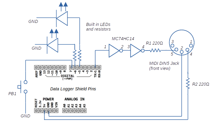
The CircuitHere is a schematic of the circuit used in this project:
- The schematic does not show the 5V power and ground connections required for the MC74HC14 chip. These are wired: 5V to pin 14 and Ground to pin 7.
- The two LED’s and resistors are built into the shield. To use them, bridge Arduino Pin 5 and 6 to the L1 and L2 thru holes.
- The midi stream is sent from the TX pin of the Arduino. By default, this is wired to pin 1 on an Arduino board. In the program, a Serial.write command will send the midi commands to pin 1 and on to the midi output circuit.
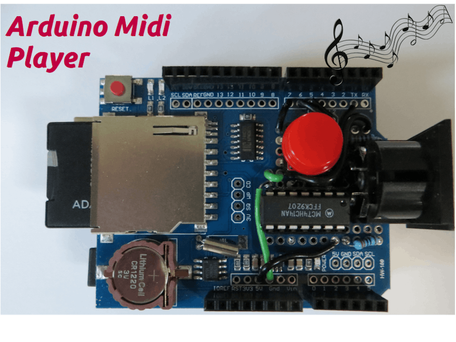
The circuit as shown is wired up on the prototype area of the shield. This requires some fine work but is possible. Here is a picture of the completed shield.
As an alternative, the circuit can be constructed on a solder less breadboard. Refer to an article at www.midi.orgthat describes this approach
https://www.midi.org/midi-articles/arduino-midi-output-basics
Once this is complete, connect the shield to the Arduino
In order for the code to work, the following libraries need to be installed.
- SdFat (library used to access the SD Card)
- MD_MIDIFile (library used to play midi files from the SD Card)
Use Tools → Manage Libraries to install. Screenshot below:
The documentation for the Midi library is located at these two links
https://github.com/MajicDesigns/MD_MIDIFile
https://majicdesigns.github.io/MD_MIDIFile/
The examples included in the GitHub repository give an overview of how the library works. Also, some example midi files are included.
Play Midi FileTo play a midi file, follow the following steps:
- Load a midi file on the formatted SD card. The file name cannot be more than eight characters followed by the extension “.mid”
- Open the sketch “MinimalMidiPlayer” in the Arduino IDE
- In the Arduino sketch, change the declaration line [const char *loopfile = “LOOPDEMO.MID”] to specify the file on the SD Card
- Make sure SD_SELECT = 10
- Upload the sketch to the Arduino
- Disconnect the Arduino from power source
- Insert the SD card into the reader.
- Connect the midi output jack via a midi cable to a synthesizer or midi player.
- Connect the Arduino to a power source. Don't use the USB connector to provide power, it may not have enough capability to power the shield and Arduino. Rather use a source connected to the DC in jack on the Arduino
- Push the button on the shield and the song will play. Success!
#include <SdFat.h>
#include <MD_MIDIFile.h>
#define SERIAL_RATE 31250 // Midi standard serial rate is 31250 baud
#define ARRAY_SIZE(a) (sizeof(a)/sizeof((a)[0]))

const byte SD_SELECT = 10; // Chip select for Sd card is pin 10
const char *loopfile = "LOOPDEMO.MID"; // pointer to midi file on SD card
const int buttonPin = 7;    // the number of the pushbutton pin
const int ledPin = 6;      // the number of the LED pin
bool playFile = false; // boolean variable indicating if a file should be played


SDFAT  SD;
MD_MIDIFile SMF; // create an instance of a midi file

// Called by the MIDIFile library when a file event needs to be processed
// thru the midi communications interface.
// This callback is set up in the setup() function.
void midiCallback(midi_event *pev){
  if ((pev->data[0] >= 0x80) && (pev->data[0] <= 0xe0)){
    Serial.write(pev->data[0] | pev->channel);
    Serial.write(&pev->data[1], pev->size-1);
  }
  else {
    Serial.write(pev->data, pev->size);
  }
}

void setup() {
  pinMode(buttonPin, INPUT_PULLUP); // use built in pullup resistor with push button
  pinMode(ledPin, OUTPUT);
  digitalWrite(ledPin, LOW);

  Serial.begin(SERIAL_RATE);

  // Initialize SD Card
  if (!SD.begin(SD_SELECT, SPI_FULL_SPEED)){
    while (true) ;
  }

  // Initialize MIDIFile
  SMF.begin(&SD);
  SMF.setMidiHandler(midiCallback);
  SMF.looping(false);
}

void loop() {
  // Wait for pushbutton input
  int reading = digitalRead(buttonPin);
  // If push button is depressed, load midi file and switch on LED
  if (reading == LOW) {
    playFile = true;
    digitalWrite(ledPin, HIGH); // Switch on LED
    SMF.load(loopfile);
    }

  // play the file if playFile is true
  if(playFile == true){
  // Play until end of file is reached
    while (!SMF.isEOF()){
    SMF.getNextEvent();
    }
  }
  // Once file is finished playing, close midi file and switch off LED
  playFile = false;
  digitalWrite(ledPin, LOW);
  SMF.close();
}As an enhancement to this minimal midi player, it is possible to play multiple songs from the SD Card. Here are the instructions:
- Load multiple midi files on the SD Card. The files must all be in the root directory. Files in sub folders will not play. The file names cannot be more than eight characters and must be followed by the extension “.mid”
- Open the sketch “MultiTrackMidiPlayer” in the Arduino IDE. Adjust the delay (approx line 82) to allow for longer or shorter pauses between songs
- Make sure SD_SELECT = 10
- Upload the sketch to the Arduino
- Disconnect the Arduino from power source
- Insert the SD card into the reader
- Connect the midi output jack via a midi cable to a synthesizer or midi player
- Connect the Arduino to a power source. Don't use the USB connector to provide power, it may not have enough capability to power the shield and Arduino. Rather use a source connected to the DC in jack on the Arduino
- Push the button on the shield and the songs will play in sequence until all songs are played. Success!
This is a minimal player and and does not have all the possible error checking built into the code. Some additional development would be needed to add additional features.


_ztBMuBhMHo.jpg?auto=compress%2Cformat&w=48&h=48&fit=fill&bg=ffffff)


_3u05Tpwasz.png?auto=compress%2Cformat&w=40&h=40&fit=fillmax&bg=fff&dpr=2)
Comments
Please log in or sign up to comment.