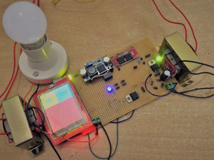
Switchboards are available in all forms and designs. They find application in every household electrical wiring. Switchboards provide electrical insulation from the live circuit, but sometimes these boards fail to perform their jobs under certain circumstances. The reasons could be many as follows: 1. material used in switch may degrade over time and lose their dielectric property. 2. Wet hands sometimes create contact with the live circuit. 3. Under extreme heat, sometimes the switches undergo deformation.
Thus these switchboards do not completely provides electrical insulation for the user. To solve this I have come up with the idea of replacing the mechanical switches with TFT-LCD panels which offer complete isolation from the live electrical circuit running behind your switchboards.
Advantages of this piece of technology: 1. Smaller Footprint compared to traditional switches. 2. Noise free. 3. Efficient and have longer service life. 4. Inexpensive 5. Easy to install and use.
WARNING:THE PROJECT DEALS WITH 230 VOLTS AC POWER. IMPROPER OR INCORRECT USE CAN CAUSE DEATH OR INJURIES AND PHYSICAL DAMAGE TO APPLIANCES. PROPER CARE AND PROTECTION MUST BE EMPLOYED BEFORE WORKING ON THIS PROJECT.
Journey into making this HardwareThe hardware involves Power Electronics at its core and Digital electronics at the front-end.
Power Electonics Circuitry : Involves the following components
- Full Wave Bridge Rectifier *2
- DC-DC Boost Converter
- DC-DC Isolated converter
- 220/12 VAC 0.5A Step Down Transformer
DigitalElectronics Circuitry : Involves the following components
- 2.4 inch TFT touch panel.
- Micro-controller-ArduinoUNO
Power electronics performs the main job of switching CoolMOS C7 while the Digital electronics forms a user interface.Thus meeting the problem statement we have stated, that is providing isolation from lethal power.
CoolMOS C7 MOSFET as a SwitchMOSFET are uni-directional semiconductor switches and are very well known to work with DC power.
The challenge
Almost every household devices operate on AC power. We know the advents of AC power and is altogether a different discussion, the question that is of prime concern is, "Can we employ MOSFET's with AC Power?"
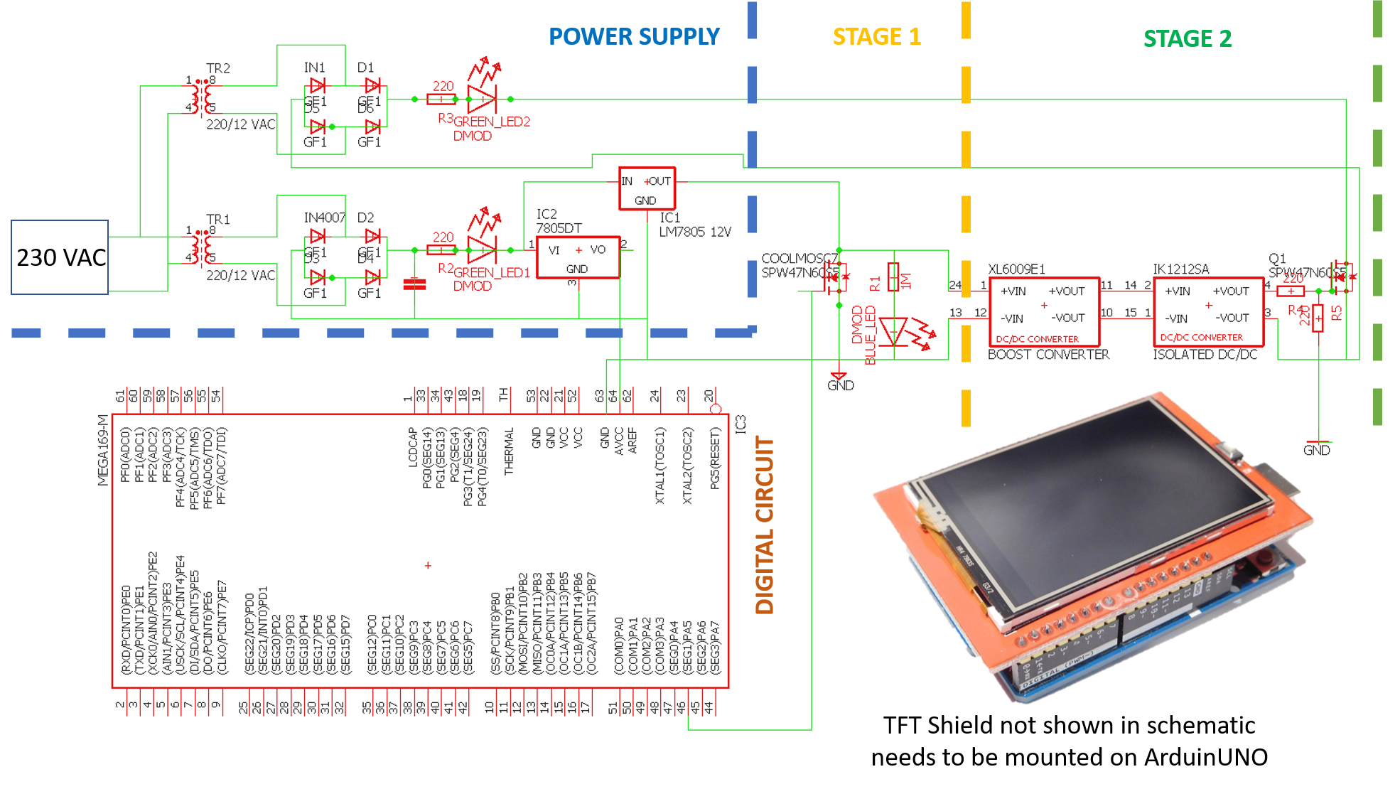
Step 1: Every Problem Has a Solution!!!As shown in the schematic, the MOSFET is connected to the output of Bridge Rectifier with an AC load in series with one of the Line input to the Bridge Rectifier. We can control AC home appliances with MOSFET.
NOTE 1: The MOSFET still sees a DC Voltage. Whenever the CoolMOS C7 MOSFET is switched on, the bridge rectifier draws current from the AC source and the drives the load respectively.
NOTE 2: Do not connect mains supply (230V, 50Hz In India) directly to the Bridge rectifier if you are using IN4007 Diodes. That is why I have made use of 2 transformers. This transformer(Auxiliary transformer) is not necessary if you can find diodes with high power tolerance.
Step 2: Building Power SupplyA step down transformer is used to step down 230 V to 12 V AC which is then passed through the Bridge Rectifier and filtering capacitor. At the output we receive around 14V DC which is fed to Linear Voltage Regulator LM7805 and LM7812 IC.
LM7805 provides regulated 5V which will be used to control the MCU(Micro Controller Unit) LM7812 provides regulated 12V which will be used by the Gate Drive Circuit.
Step 3: CoolMOS Stage 1 Gate Driver CircuitThis project will comprise of two stage Gate Drive circuit. CoolMOS C7 has Gate Threshold voltage as 3V (min).
For stage 1 gate drive, 5V DC will be applied across gate and source which is generated by ArduinoUNO (Refer Step # to learn how). Drain is connected to +12V of the LM7812 voltage regulator IC and source is connected to common ground of both micro-controller and the system.
Step 4: CoolMOS Stage 2 Gate Driver CircuitNow we will utilize the Drain to Source voltage controlled by Microcontroller driven stage 1 gate drive to turn on CoolMOS C7 controlling the AC load.
To turn on CoolMOS properly, 12 volts Gate to Source voltage should be good enough. But this gate drive voltage must be isolated. This is achieved by using the XL6009E1 DC-DC Boost Converter and IK1212SA Isolated DC-DC Converter. By doing so we have isolated stage 1 and stage 2 Gate Drive circuit and coupled them through Power Isolation.
Step 5: Drain and Source Connection for Stage 2The stage 2 CoolMOS is the one which behaves as a switch having control over driving the AC Load and this CoolMOS C7 of stage 2 receives Gate pulse through stage 1 CoolMOS C7 switching.
Step 6: User Interface Using TFT DisplayNow that we have successfully built the gate driver for our CoolMOS C7. We will now work on the user interface.
For this we will be using the 2.4 Inch TFT LCD SPFD5408 With ArduinoUno,through which we will design graphics indicating ON and OFF keys to set up our Flat Panel Switchboard.
This TFT Shield when mounted on AduinoUNO, we use Analog Pin A5 which is set to LOGIC 1 when user touches ON and LOGIC 0 when OFF is touched.
This LOGIC controls the CoolMOS C7 in stage 2 gate drive circuit correspondingly.
Watch It Perform!!!Applying 220 VAC across the diode in the bridge rectifier will burn them dead as it did in my case. Therefore I have used Auxiliary Transformer (not needed if your diodes can tolerate high power rating). I have used 220-230V, 50Hz 0.5W Philips Bulb running on auxiliary transformer secondary rated at 12 VAC 0.5A 50Hz, thus the bulb glows very dim in the video.
EDITSThe circuit contradicts the very fact of smaller footprint , just because there has been a delay from the manufacturer to deliver my customized PCB. So i had to go on submitting with my prototype circuit.


_ztBMuBhMHo.jpg?auto=compress%2Cformat&w=48&h=48&fit=fill&bg=ffffff)


Comments
Please log in or sign up to comment.