Hackster is hosting Hackster Holidays, Ep. 7: Livestream & Giveaway Drawing. Watch previous episodes or stream live on Friday!Stream Hackster Holidays, Ep. 7 on Friday!
Juan Santana
Published © GPL3+

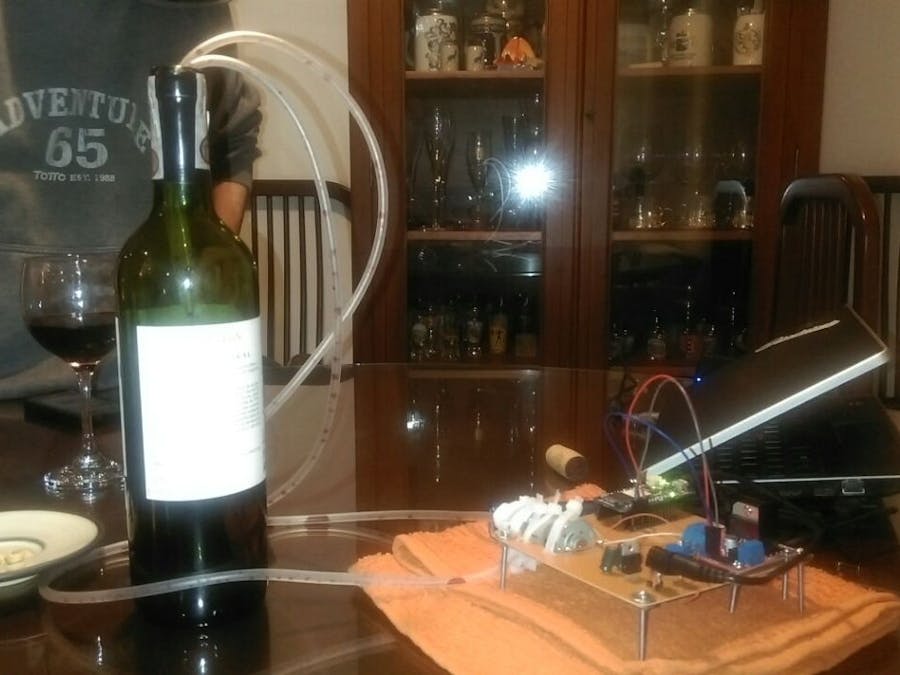
IoT Wine-Tender-Arduino MKR1000!

This circuit serves a wine using a mini water pump all controlled from your phone. Enjoy it during your holidays!

IntermediateShowcase (no instructions)16 hours2,635
IoT Wine-Tender-Arduino MKR1000!

Things used in this project

Hardware components

Arduino MKR1000
Arduino MKR1000
×1
DC motor (generic)
×1
Dual H-Bridge motor drivers L298
SparkFun Dual H-Bridge motor drivers L298
×1

Software apps and online services

Evothings Studio
Evothings Studio
Arduino IDE
Arduino IDE

Hand tools and fabrication machines

CNC Machine

Story

Read more

Custom parts and enclosures

Wine to PCB

The idea is to see the files involved to create a PCB using a CNC

Code

Wine

Arduino
#include <SPI.h>
#include <WiFi101.h>

// Setup  WIFI 
char ssid[] = "xx";       //  your network SSID (name)
char pass[] = "xx";   // your network password
int status = WL_IDLE_STATUS;
WiFiServer server(80);
//int keyIndex = 0;           // your network key Index number (needed only for WEP)

//Setup your inputs and/or outputs
int o_MotorDir1 = 7;
int o_MotorDir2 = 8;
int o_MotorEnaPwm = 10;

int wifi_led_pin = 6;
//int WinePin = 7;

//Setup general variables
int val = 0;
int val_AnalogIn_A = 0;
int var = 0;

//Main setup section
void setup() {
  Serial.begin(9600);      // initialize serial communication
  delay(5000);

  //Setup start
  Serial.println("Setup Start, wait...");
  delay(1000);

  //setup input and output pins, this case is for Arduino MKR1000
  pinMode(o_MotorDir1, OUTPUT); // control the motor dc "giro" direction
  pinMode(o_MotorDir2, OUTPUT); // control the motor dc "giro" direction
  pinMode(o_MotorEnaPwm, OUTPUT); // enable the motor DC and at the same time ctrols the "giro" speed
  pinMode(wifi_led_pin, OUTPUT);  // LED on MKR1000 board to indicate the WIFI status, ON is connected to WIFI

  // default setup after boot for the ouput pins
  digitalWrite(o_MotorDir1, LOW); 
  digitalWrite(o_MotorDir2, LOW);
  digitalWrite(o_MotorEnaPwm, LOW);
  digitalWrite(wifi_led_pin, LOW);

  // To Test Sensors     
  //pinMode(A1, INPUT);
  //pinMode(A2, INPUT);


  // attempt to connect to Wifi network:
  while ( status != WL_CONNECTED) {
    Serial.print("Attempting to connect to Network named: ");
    Serial.println(ssid);                   // print the network name (SSID);

    // Connect to WPA/WPA2 network. Change this line if using open or WEP network:
    status = WiFi.begin(ssid, pass);
    //wait 10 seconds for connection:
    delay(10000);
  }
  server.begin();                           // start the web server on port 80
  printWifiStatus();                        // you're connected now, so print out the status
}


void loop(void) {

  //in case you have sensors connected to Analog Input (A1 and A2) here will be read and send to the serial monitor.
  //read_Analog_input();
  
  // Check if module is still connected to WiFi.
  if (WiFi.status() != WL_CONNECTED) {
    while (WiFi.status() != WL_CONNECTED) {
      
    }
  }

  WiFiClient client = server.available();

  if (client) {
    
    //Serial.println("Client connected.");

    while (client.connected()) {
      if (client.available()) {
        char command = client.read();
        if (command == 'H') {
          digitalWrite(o_MotorDir1, HIGH);
          //Serial.println("LED is now on.");
        }
        else if (command == 'L') {
          digitalWrite(o_MotorDir1, LOW);
          //Serial.println("LED is now off.");
        }
      }
    }
    //Serial.println("Client disconnected.");
    client.stop();
  }
  

}


void printWifiStatus() {
  // print the SSID of the network you're attached to:
  Serial.print("SSID: ");
  Serial.println(WiFi.SSID());

  // print your WiFi shield's IP address:
  IPAddress ip = WiFi.localIP();
  Serial.print("IP Address: ");
  Serial.println(ip);

  // print the received signal strength:
  long rssi = WiFi.RSSI();
  Serial.print("signal strength (RSSI):");
  Serial.println("it means:");
  Serial.println("-30 dBm Amazing");
  Serial.println("-67 dBm Very Good");
  Serial.println("-70 dBm Okay");
  Serial.println("-80 dBm Not Good");
  Serial.print(rssi);
  Serial.println(" dBm, now we have!!!");
  // print where to go in a browser:
  Serial.print("To see the app in action, use IP-Address in your Phone app GUI: ");
      digitalWrite(wifi_led_pin, HIGH);

  
  Serial.println(ip);
  delay(5000);

  
}

void read_Analog_input()
{
  while(var < 10)
  {
    if (var == 0)
    {
      Serial.println("In case to have sensors here are printed the Values in Analog Input");
    }
  // do something repetitive x times
  val_AnalogIn_A = analogRead(A1);
  Serial.print("Analog In A1 :");
  Serial.println(val_AnalogIn_A);
  delay(100);
  var++;  
  }  
}

The APP

The files fot the APP in Evothings Studio

Arduino File

Credits

Juan Santana
3 projects • 3 followers
Thanks to 1/4 Tech.

Comments