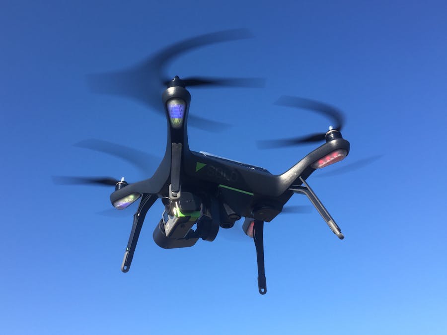
You ever wanted to have ground collision avoidance, or terrain follow with your 3DR Solo drone?
So here is what you need to do in order to add a Lidar rangefinder to the 3DR Solo. I am flying it now successfully for more than 5 months and have the sensor permanently attached to my Solo in the meantime.
Lidar is supported since Arducopter (AC) 3.2.1 via a PWM connection, and since AC 3.3 also by using the I2C bus. There are a few different brands supported in the meantime. For a complete and up to date overview please look at the Arducopter wiki. The following blog focuses on the Garmin LidarLite (formerly PulsedLight) due to its convenient form factor and low weight which makes it perfectly suited for Solo.
A word of caution before you proceed: All in the following described modifications require a great portion of care and good RC building skills are mandatory. Please also read the Arducopter wiki on the LidarLite sensor to be familiar with its capabilities and limitations. This project will void your 3DR warranty.
Prerequisites:- Completed breakout of the I2C bus interface to the accessory bay port, see the following Hackster blog
- You know how to install a new Flight Controller firmware, see 3DR Solo developer guide
- You should be familiar with Mission Planner
- A LidarLite V2 or V3 Sensor
Note: Do not use the first generation LidarLite V1 sensor since its having issues with connectivity through I2C.
Connecting LidarLite to I2CThe LidarLite sensor can be connected via PWM or I2C. Unfortunately the required PWM ports of the Pixhawk 2 flight controller are not broken out on the Solo mainboard. Therefore we will use the I2C bus which is accessible by tapping into the Solo compass lines. Please follow the instructions in the referenced Hackster blog on how to break out the I2C bus to the extension port in the accessory bay. For the initial setup you may use an accessory bay breakout board as explained in the blog.
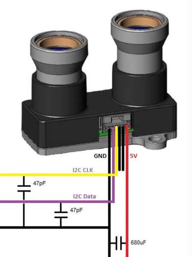
Next, we need to add a low pass filter in order to filter potential noise on the I2C bus caused by the sensor. Therefore we apply 2 47pF capacitors between ground and the respective I2C line, and a 680uF capacitor between ground and +5 power as shown now the picture below.
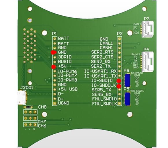
Now we connect the sensor to the respective pins on the board. The pins are explained in the 3DR development guide.
If you followed the Hackster blog referenced above on the I2C breakout, IO-SWDIO and IO-SWDCLK are used for the SCL (I2C CLK) and SDA (I2C Data) lines of the I2C bus.
The sensor can now be mounted onto the breakout board. Please see the following picture as an example about how I did it.
The Lidar drivers are only included in AC 3.3 and higher. Unfortunately 3DR decided to step back to the older AC 3.2 codebase with the current firmware. In order to get Lidar and all the other nice enhancements of Arducopter 3.3 running on Solo, you need to deploy another firmware version. A well tested candidate is the Solo-rebase 2.4.1-3 release, which was part of the Solo beta testing. It is available on the 3DR GitHub.
To install the .px4 file, please follow the instructions here.
Note: The 2.4.1-3 release requires a full compass and level calibration. The only incompatibility compared to the current Solo firmware I noticed so far is that the LED lights cannot be changed with the Solex app. Otherwise everything works along with the 3DR app on Android, iOS and with Solex.
Configure the LidarLite sensor in Mission PlannerOpen Mission Planner on your PC and connect to Solo WiFi. Go to the Full Parameter list and set the following parameters:
- RNGFND_TYPE = 4 (I2C bus)
- RNGFND_MAX_CM = 1000 (range set to 10 meters, LidarLite operates up to 40 meters range)
- RNGFND_MIN_CM = 20. 20 cm minimum range is the optimum. Below that distance you will still get readings, but they may be inaccurate (the optics can start to introduce parallax error if the sensor picks up signal from specular reflections rather than directly from a return signal).
Distances read by the sensor can be seen in the Mission Planner’s Flight Data screen’s Status tab. Look closely for “sonarrange”. Connect Solo and move Solo up and down to check that the value for "sonarrange“ is changing accordingly. In case you get no reading, try to swap the I2C lines.
The following video shows the sensor in action. Please note that Lidar only works in FLY, FLY Manual, and Land modes.
Custom printed housingLast but not least we may want to add a nice housing for the sensor. Therefore I designed a custom shell. You find the STL print files in the files section below. It includes the mount for the Molex connector so you don't need the accessory bay breakout board anymore.
The pinout for the accessory bay port can be found in the 3DR developer documentation here. The mating connector part number is JAE SJ038252 and can be purchased on Mouser.
In addition, you may add here also a USB port to the IMX in order to add other applications, such as a Lidar-based front-facing collision check and obstacle avoidance. Therefore, see this project here.


Comments
Please log in or sign up to comment.