This tutorial is from BreakoutBros.com. See the full version here.
A relay is an electro-mechanical device that uses an electromagnetic field to close a switch. The benefit of a relay is that it is isolated from the circuit that is being switched. This provides a safer isolation for your circuit and makes the design of the circuit very simple. The one downfall of the relay is that they will wear out more quickly than other switching devices such a triacs or IGBTs. They are also generally more expensive for the comparable application using the other devices. We will go over how to properly bias and control it using an Arduino or your choice of an equivalent device. The Elegoo Uno R3 Starter Kit has provided us with all the parts we will need to build this circuit.
For this tutorial you will need:- SRD-05VDC-SL-C 5V Relay
- NPN Transistor(We used PN2222A)
- 2k Resistor
- Wires
- Arduino or Equivalent
- 26W light bulb
- Lightbulb AC fixture
- Power Supply for Arduino
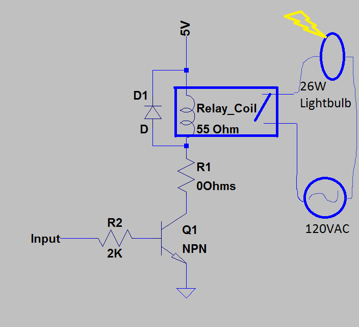
The circuit used to control the relay is below:
For this tutorial we’ll be using an Arduino equivalent, the RoboRed from Yourduino. To not overpower the I/O pins on the RoboRed, a transistor will be used to source the current to the relay from the Arduino’s power supply instead of an IO pin. The IO pin will then be on the base of the transistor, turning the transistor on and off. An NPN transistor will be used. All that needs to be ensured for the transistor is that it is held in saturation. The current requirement for saturation for the PN2222A transistor is 0.1mA. We will use a 2K resistor for R2 which gives us 5V/2kohm = 2.5mA base current , well into saturation of the transistor.
The next current we need to set is the current through the Relay coil. The SRD-05VDC-SL-C relay datasheet states that the nominal current needed for this is 89.3mA. We will size the R1 to provide this current. The coil resistance is stated to be nominally 55ohms. This means we have to take account for this when sizing R1. The other part of the circuit that should be taken account of is the VCE_sat(Collector to Emitter voltage in saturation) of the transistor. Looking at the PN2222A transistor datasheet for the PN2222 the worst case VCE_sat for our given transistor collector current and base current is about 0.1V.
With a 5V supply and a 0.1V drop over VCE, the voltage across R1 and the coil of our relay is 4.9V. Now we need to size the resistance of R1 so that 89.3mA goes through the coil. To do this we will use the equation V=IR(Voltage = Current* Resistance). For our equation, 4.9V = 89.3mA * R or R = 4.9V/.089A = 55.05hms. So now we need R1 plus the coil resistance to equal the 55.05 Ohms. This will require .05ohms which is basically 0 ohms. Even if we put 0.5Ohms for R1 the coil current change will be very small. It will be OK to just not use R1 and connect the coil directly to the collector of the transistor.
Please note: due to the coil current and tolerances of the circuit, this leaves almost no margin for this design. Over a wide range of temperatures and/or voltage supply variations and resistor/coil tolerances this design will not hold up and the switch of the relay may not be “guaranteed” to be closed. I would not suggest using this relay for anything needing high reliability or in any temperate climates. For the purpose of this tutorial and likely most of your projects, we can still use this relay. If you need higher reliability you should go with a higher voltage coil relay such as the 12V or 16V options. It will make it easier to guarantee the correct coil current.
The last thing to check is to make sure the relay is rated for the load – in this case the light bulb. We will be using a 26W light bulb. At 120VAC this give us 26W/120Vac = .216A. The contact rating of this relay is 10A at 120VAC so we have plenty of margin for this load.
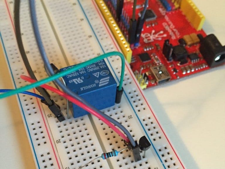
Step 2Now we will wire up the relay on the bread board and use a 26W light bulb lamp to display the functionality of the relay. If you are not familiar with AC circuits please look for some safety tips on using an AC circuit. You should never be cutting or stripping wires while the circuit is live. We will connect the light bulb as shown in the circuit below:
First we will strip the AC cord of the Light Bulb to break L1 of the bulb. This will then go to either side of the switching relay. Now when the relay closes, the circuit will complete for the light bulb and the bulb will light up.
Now we will use Pin 3 of the RoboRed Yourduino to open and close this relay which will turn on and off the light. When Pin 3 goes high it will turn on the transistor which will close the relay. When pin 3 goes low the transistor will be off and no current will go through the relay, opening the relay. The code will cycle this every 3 seconds. Starting out the relay will be open for the first 3 seconds then the relay will be closed for the next 3 seconds, turning on the light, and then for the next 3 seconds the relay will open, turning off the light…this will continue until the Arduino is turned off or the light bulb burns out. The code used is below. You can download the Relay Tutorial code here.
// BreakoutBros Relay Tutorial
// 2016
//This tutorial is using the RoboRed Arduino from Yourduino
//Along with parts from the Elegoo Uno R3 Complete Starter Kit
void setup() {
 // initialize digital pin 3 as an output.
 pinMode(3, OUTPUT);
}
//The main loop will continue to run until the arduino loses power
void loop() {
 digitalWrite(3, LOW); // turn the relay off to start
 delay(3000); // wait for 3 seconds
 digitalWrite(3, HIGH); // turn the relay on to turn on the light
 delay(3000); // wait for 3 seconds
}
Write this sketch to your Arduino of choice and now you have it, a low voltage signal powering a higher current AC light Bulb using a relay.
DemoIf you liked this write up you may want to subscribe to get updates from BreakoutBros!


_ztBMuBhMHo.jpg?auto=compress%2Cformat&w=48&h=48&fit=fill&bg=ffffff)


Comments