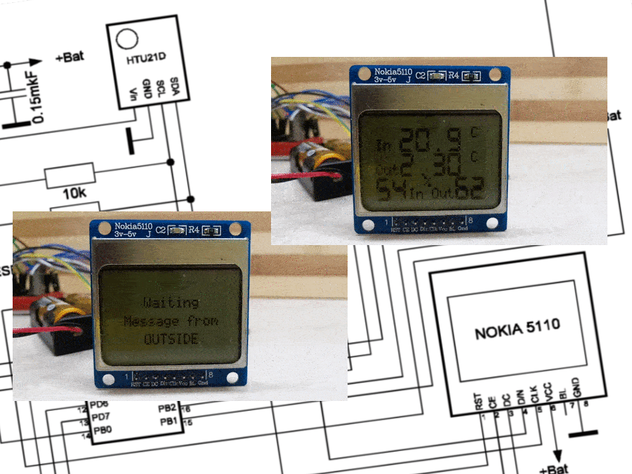
To begin with, I could not find an amateur weather station or a battery-powered thermostat on the Internet. I mean a simple household autonomous weather station with the measurement of parameters indoors, outdoors and displaying information on the display of the weather station. Hobbyists do not stop at this problem, but power their autonomous devices from solar panels or batteries. Since my surfing on the Internet did not give anything, I realized that this is not a simple problem and began to study it.
To reduce the cost of goods, manufacturers of industrial autonomous devices compose programs taking into account the amount of memory where the codes of these programs are written. After all, memory is money. The smaller the memory size, the lower the cost of the product. It is very difficult to do this on the Arduino IDE platform, since everything is hidden in bulky heavy libraries, and simple codes (sketches) take up several dozen lines in the editor, making work in this environment comfortable and not requiring much effort. I will give a good example: the size of the memory occupied in the controller by the blinking code of one LED written in the Arduino platform is 1030 bytes, in C - 176 bytes, and in the low-level programming language Assembler - 42 bytes. At the same time, industrial household weather stations, room thermostats have been running for years on a pair of AA batteries, and this fact is the goal that I would like to achieve.
To reduce the cost of goods, manufacturers of industrial autonomous devices compose programs taking into account the amount of memory where the codes of these programs are written. After all, memory is money. The smaller the memory size, the lower the cost of the product. It is very difficult to do this on the Arduino IDE platform, since everything is hidden in bulky heavy libraries, and simple codes (sketches) take up several dozen lines in the editor, making work in this environment comfortable and not requiring much effort. I will give a good example: the size of the memory occupied in the controller by the blinking code of one LED written in the Arduino platform is 1030 bytes, in C - 176 bytes, and in the low-level programming language Assembler - 42 bytes. At the same time, industrial household weather stations, room thermostats have been running for years on a pair of AA batteries, and this fact is the goal that I would like to achieve.
I present my version of the weather station with new algorithms, element base and code with low-level inserts. All this made it possible to reach the operating time of the weather station from one set of batteries, even somewhat more than manufacturers of household weather stations and room thermostats guarantee.
What is done:
A transition to a stable controller frequency (8 MHz) was made at a supply voltage below 3 V. To reduce the amount of memory occupied in the sketches, some C/C++ functions were used. The main thing is that the algorithm for transmitting packets from an external temperature and humidity sensor and the algorithm for receiving these packets by the weather station base have been fundamentally changed. To ensure reliable reception of packets from an external sensor, not one, but three packets with data on outdoor air parameters and battery status are formed and sent at an interval of about 0.3 seconds. Only after sending the third packet, the controller of the external sensor, together with the periphery, goes to sleep. The weather station base goes to sleep after receiving one of the six packets from the external sensor and wakes up half a second earlier in a minute before the next series of packets from the external sensor arrives.
The weather station consists of two autonomous nodes powered by two AA batteries: a base and an external sensor.
The base is built on the ATMEGA328P controller. It measures the temperature and humidity (temperature and humidity sensor HTU21D) in the room, and also measures and analyzes the power supply voltage of the node, which is provided by two 1.5V AA batteries. The controller also receives a signal from the LoRa receiver, which receives data from external sensor. All information from the controller is displayed on the LCD display of NOKIA 5110.
The external sensor, also assembled on the ATMEGA328P controller, measures the temperature and humidity of the air outside (HTU21D module), as well as the supply voltage of the external node on two AA batteries 1.5 V. The LoRa transmitter of this node transmits data on temperature, humidity and battery status to the base. 3 packets are sent from the external sensor with an interval of about 0.3 seconds, then the ATMEGA328P controller, the LoRa transmitter and the HTU21D module are put into sleep mode to conserve battery power. Measurements and sending data from an external sensor are performed with a cycle slightly less than 1 minute.
The operation of the database is built according to the following algorithm:
First, when both nodes of the weather station are turned on, the base controller sends commands to measure the temperature and humidity inside the room and displays these parameters on the display, then sets the LoRa receiver to the broadcast listening mode. After receiving a signal from an external sensor and successfully decoding the received data, the controller issues a command to re-measure the temperature and humidity and displays the data in full on the screen. Then the base goes to sleep, waking up about half a second before the planned arrival of a signal from an external sensor. Having received and decrypted one of the three packets from an external sensor, it re-performs its measurements, displays information on the display and goes back to sleep. If for some reason there is no signal from the external sensor for about one minute (for example, the batteries are dead), which corresponds in time to sending 6 packets from the external sensor, the base takes measurements only indoors, occasionally scanning the air: what if the external sensor appears on the air ?! This is done so that the LoRa module, which is constantly working on receiving the radio, does not discharge the batteries of the base in a short time.
To assemble the device, you will need radio components:
- Controller ATMEGA328P-PU — 2 pcs.
- Humidity and temperature sensor HTU21D/SHT21/Si7021 — 2 pcs.
- LCD display NOKIA 5110 — 1 pc.
- Receiver-transmitter LoRa Ra-01 — 2 pcs.
- Breadboard (fiberglass), mounting wires, AA batteries, 8 MHz quartz resonators, resistors, capacitors, and other little things.
The cost of components at the prices of the AliExpress website is about $ 25.
Changing fuses and loading code into controllersAs a programmer, when working with ATMEGA328P controllers, I use the Arduino UNO board.
It is necessary to install the Arduino as ISP bootloader in new controllers and it must be taken into account that the ATMEGA328P controllers go on sale with a factory fuse setting to monitor (control) the supply voltage above 2.7V. We will work on batteries, the voltage on which, when discharged, can be below the factory-set threshold of 2.7V, and with an 8 MHz crystal. Install the bootloader and change the fuses to our conditions, using the Arduino UNO board as a programmer, in the following sequence:
- Find the boards.txt file at c:\Program Files\Arduino\hardware\arduino\avr\ and open it with a text editor with formatting, for example, AkelPad.
- Pad the file with a block and save the file.
amega.name=Mega Low (8 MHz, >1.8V)
amega.upload.tool=avrdude
amega.upload.protocol=arduino
amega.upload.maximum_size=32256
amega.upload.maximum_data_size=2048
amega.upload.speed=57600
amega.bootloader.tool=avrdude
amega.bootloader.low_fuses=0xFF
amega.bootloader.high_fuses=0xDA
amega.bootloader.extended_fuses=0xFE
amega.bootloader.unlock_bits=0x3F
amega.bootloader.lock_bits=0x0F
amega.bootloader.file=optiboot/optiboot_atmega328.hex
amega.build.mcu=atmega328p
amega.build.f_cpu=8000000L
amega.build.board=AVR_UNO
amega.build.core=arduino
amega.build.variant=standard
- Upload the ArduinoISP.ino sketch from the Arduino IDE platform examples to the Arduino UNO board (File –> Examples –> ArduinoISP).
- Assemble a circuit (Arduino UNO board, ATMEGA328P controller, 16 MHz quartz) for installation in the ArduinoISP bootloader controller, connect it to the computer and write the Arduino as ISP bootloader to the controller.
- Replace the quartz in the 16 MHz circuit with 8 MHz. In the TOOLS menu, select the Mega Low (8 MHz, > 1.8V) board from the list, which appeared in the menu after adding a new block to the boards.txt file, select the Programmer: “Arduino as ISP” and, by clicking Write bootloader, change fuses and others settings in the controller.
- Next, we load the necessary sketch into the controller using the same scheme as for installing the bootloader, via Sketch –> Download via the programmer.
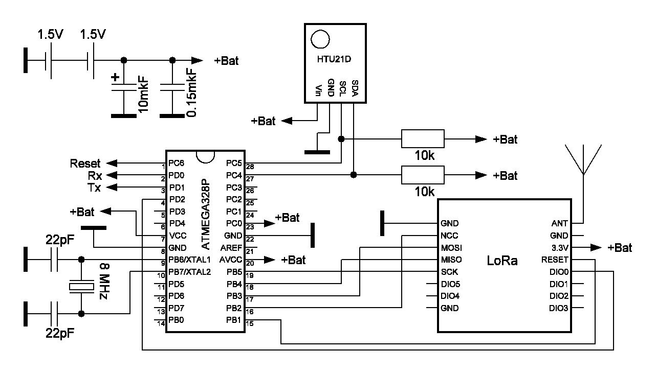
The external sensor is based on the ATMEGA328P controller. It receives data from the HTU21D using the I2C protocol, measures and analyzes the node supply voltage, and controls the LoRa transmitter.
Electrical diagram of the external sensor:
The HTU21D module is powered and pulled up from pin 14 of the ATMEGA328P controller. This is done in order to programmatically reset the power of the HTU21D and put this sensor into low power mode during sleep.
In the external sensor, three packets are formed and sent at intervals of about 0.3 seconds with data on the temperature and humidity in the street and the state of the batteries. If the voltage on the batteries is above the set threshold (2.2V), then BGood is present in the package code, and BLow is below. After sending the third packet, the controller of the external sensor, together with the peripherals, go to sleep. The cycle of sending a series of packets is 53.5 seconds.
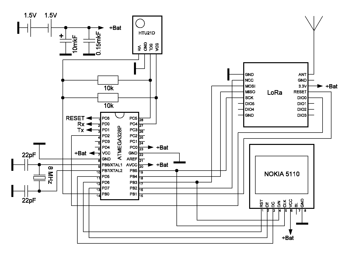
The brain of the base is the ATMEGA328P controller. It receives signals from the HTU21D sensor using the I2C protocol and interacts with the LoRa receiver and the NOKIA 5110 display via SPI.
The work of the base begins in Setup with the initialization of modules, measurement of air parameters, analysis of battery voltage and displaying this information on the display (see base sketch). Further, already in the Loop, the air is listened to by the LoRa receiver. After receiving and decoding the signal from the external sensor, measurements are repeated, the voltage on the batteries is analyzed and the measured and received data are displayed on the display. Having done this work, all elements of the circuit go to sleep for about half a second less than the period of sending packets from an external sensor. In the next cycle, the controller wakes up and turns on the receiver approximately 0.5 seconds before the expected arrival of a signal from an external sensor. Thus, the base controller and peripherals operate with the same period (cycle) as the external sensor - somewhat less than a minute (53.5 seconds). If the radio signal from the external sensor does not arrive at the analyzer's receiver for approximately one minute (this is the time sufficient to receive one of the 6 packets), the analyzer enters the mode without an external sensor for 4 hours, measuring air parameters and evaluating the condition of the batteries only in room with indication on the display of these data. At the end of a four-hour cycle of analyzer operation without an external sensor, it again listens to the air: what if the external sensor reappears on the air?
To transfer the HTU21D module to low power consumption mode during sleep, its power, as well as in the external sensor, is organized from the ATMEGA328P controller (pin 14).
In general, the following picture is visible on the base display:
The display of the NOKIA 5110 is densely packed with characters due to the low resolution and small screen size. This picture would look much better on a modern e-ink display. In the future, I will use the e-paper display in my projects.
Battery life and moreTo calculate battery life, you will need time and current consumption during work (operating time) and sleep. The operating time and operating current were measured using test sketches, the idea of which is taken from here. Next, I give an abbreviated version of the calculation of the service life (resource) using the test sketches I developed. For those who are interested in test sketches and calculation methods, they can be found here.
The operating current was measured using the same test sketches. To avoid breaks in the power circuit or a significant increase in the output impedance of the batteries, you can use a 3.9... 5.6 Ohm shunt and a digital multimeter connected in parallel to it with mechanical switching in voltmeter mode in the range of 2000 μV. This is critical when measuring the base's sleep current consumption, as a power failure or severe current limiting causes the analyzer to restart cyclically. An external sensor can also go into a permanent restart. As far as possible, it is necessary to check the current consumption in different ways on different scale ranges of the device and with the batteries that you plan to use, and also without displaying the results on the Arduino port monitor.
Measurement results
Weather station base
- Operating time of air measurement function, battery status: 0.39 sec
- Operating current of the air measurement function, battery condition: 3.5 mA
- Transmission/reception function operating time: 83ms
- Transmit/receive function operating current: 11.5 mA
- Sleep current: 190uA
- Battery capacity AA GP Lithium: 2900 mAh
Weather station external sensor
- Operating time of air measurement function, battery status: 0.25 sec
- Operating current of air measurement function, battery condition: 3.4 mA
- Transmission/reception function operating time: 42ms
- Transmit/receive function operating current: 30.0mA (4dB)
- Sleep current: 10uA
- Battery capacity AA GP Lithium: 2900 mAh
What catches your eye when looking at these results. The signal transmission current of the LoRa transmitter is 30.0mA with a transmitter power of 4dB. For comparison, the advertised transmit current for the nRF24L01 radio is 13.5 mA. The conclusion is obvious: you need to use nRF24L01 in your projects.
The average current consumption of the external sensor of the weather station is 0.13 mA. The capacity of the AA GP Lithium batteries for the external sensor should be enough for 2.5 years of operation. Obviously, AA batteries are not required for this weather station unit, but smaller capacity AAA batteries can be used.
The average current consumption of the weather station base is 0.27 mA. The estimated resource of AA GP Litium batteries in the base of the weather station is 1.2 years.
For example, for the Computherm Q7RF wireless room thermostat, the battery life is about 1 year. Not bad! Of course, I would like to compare it with the base of an industrial weather station, but the manufacturers of this product do not indicate the battery life in the documents. This fact can also be explained by the fact that the capacity of batteries on the market, as well as their price, differ by 2-3 times.
I will not be modest, I am pleased with the result - this is the power consumption of a weather station prototype at the level of industrial designs. And there is no limit to perfection...
I wish everyone good health in the era of covid-19 and its mutations.


Comments
Please log in or sign up to comment.