The nRF24L01 RF transceiver module has a long range with low power consumption. Long range and low power consumption determine the widespread use of radio modules in mobile devices. However, many users have difficulty connecting modules over the air. The problems are evidenced by multi-page discussions in various technical forums. I am also not one of those lucky ones who easily managed to link radio modules. The proposed method makes it easy to communicate between modules and achieve a high quality of communication.
nRF24L01 modules operate in half duplex mode. It's like talking on a walkie-talkie. Each of the correspondents at some point in time either speaks or listens. That is, each of the two nodes operates in the mode of both the receiver and the transmitter: the transmitter, having sent a message, waits for confirmation of receipt of the message from the receiver.
All the tests that I met on the Internet come down to checking the operation and communication quality of a pair of radio modules in full-function mode, when the transmitter, having sent a packet, waits for confirmation of receipt of the packet by the receiver.
I have divided this task into several simple tasks. First, the modules are checked for serviceability and correct connection (step 1). Then one of the pair of healthy radio modules is checked for operation in the transmitter mode, without waiting for a response from the other node (step 2). The last step is to improve the quality of communication in this pair of transceivers (step 3).
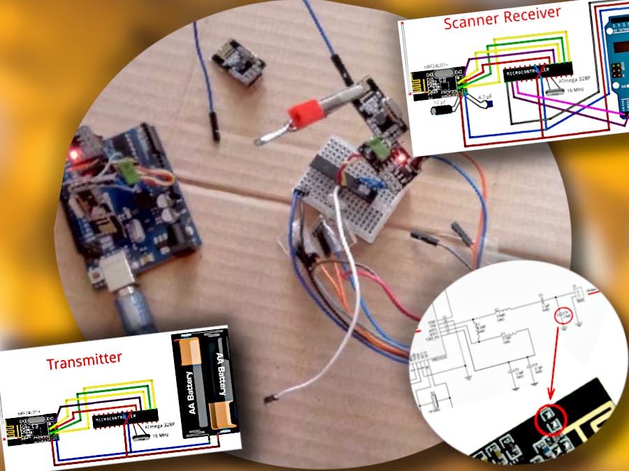
Below is a picture of the prototype.
Here are the steps.
Step 1
Upload the ether scanner sketch to the Arduino board controller, which can be found in the Arduino IDE examples: File -> Examples -> RF24 -> Scanner. This sketch is in the software (radio scanner) with a slight change. Here, the scanning time of one channel has been increased from 128 µs to 512 µs. The increase in time made it possible to identify more sources of interference and signals in one cycle of scanning the entire range. This is equivalent to replacing a measurement in a channel with the sum of four adjacent results in that channel before changing the scan time. At the same time, the time for the scanner to pass through the entire listening range slightly increased from 8 to 10 seconds.
The channel address in different sketches is given in different formats: in some -...(0x6f), in others -...(112). Translation from one format to another will become clear on the example of translation. For example, for (0x1а) it is (1+1)*16 + a =(1+1)*16 + 10 = 42. The channels count starts from 2.4 GHz, then the frequency increases by 1 MHz with the channel increasing by one.
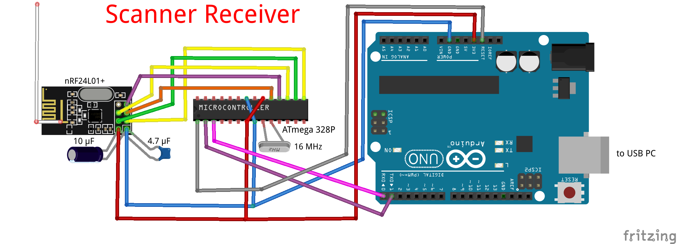
Next, we collect two nodes. This is nRF24L01+ and ATmega 328P or other controller on two breadboards. Then, one by one, we connect both nodes to the PC through the Arduino UNO board.
The power of the Arduino UNO board stabilizer is quite acceptable for connecting an additional pulse load such as nRF24L01+ with a 5V/3.3V adapter for this module or without an adapter.
On the serial port monitor of the Arduino IDE, you will see something similar.
If you saw a similar picture, then the test for the operability (healthiness) of the radio module and the correctness of its connection was successfully completed. Replace the radio module with another one you plan to work with.
Note the clear range starting from channel 4a. For me, it remains clean even if an old microwave oven is working at a distance of several meters. This is a powerful source of interference in this range. But in general, on the Internet it is recommended to choose channels for your projects above 60.
Draw your attention. At this stage, no work should be done with the soldering iron. For those who have not seen such a picture and filmed the process of unpacking the goods on video, you can contact the outlet to replace the module or return the money.
Step 2
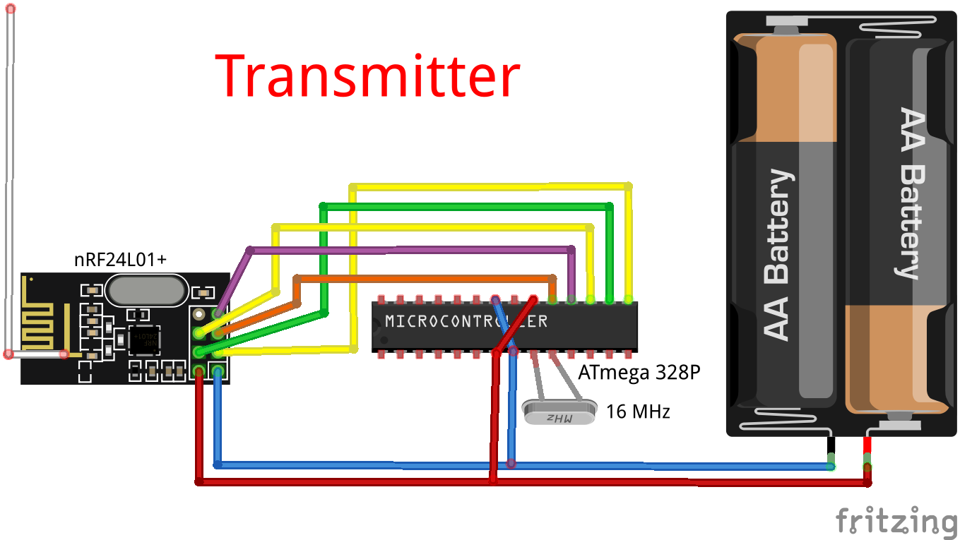
According to a scheme similar to the first, we assemble the second radio node. This will be the transmitter. Upload the transmitter sketch from the software (transmitter) to its controller.
The transmitter transmits a signal on channel 6f (112) without pauses in operation.
We supply power to the on-air scanner and transmitter. Take a closer look at what is happening on channel 6f and the channels adjacent to it. When the transmitter is on, the radio scanner will sooner or later draw one or another single-digit hexadecimal number in the 6f area, for which the transmitter is programmed. Be patient for 1 - 2 minutes, especially when working with the scanner from the Arduino IDE examples.
Step 3
Load the receiver sketch from the software (receiver) instead of the scanner.
The logic of the receiver is the same as that of the ether scanner, but, unlike the scanner, it receives signals only at the transmitter frequency 6f and, like the scanner, does not send an auto-response. The receiver exchange rate and checksum size are the same as those of the transmitter. After every 1000 listening cycles, the cycle counter is reset and information about the number of received packets from the transmitter is displayed in the Arduino IDE port monitor.
Turn on the transmitter and receiver. If the receiver receives at least every third packet, this is already a success. I couldn't get. The receiver received a maximum of 50 packets for unknown reasons.
I thought about increasing the power of the transmitted signal using an additional antenna. First, I connected the wire from the Arduino prototyping kit to the stock transmitter antenna with a clamp. Success came immediately. Received 999 packages out of 1000!
Users who want to do everything correctly will have to work hard. The additional antenna in this case is a piece of coaxial cable with a wave impedance of 50 ohms and a length of 115 mm. The antenna is connected to pin 13 (ANT2) of the nRF24L01 chip.
Now we need to solder two capacitors between the GND and VCC pins of both radio modules. A ceramic capacitor that acts as a high-pass filter with a capacity of at least 4.7 microfarads (the more, the better) and an electrolytic capacitor with a capacity of about 10 microfarads (more is possible, but useless). The high-pass filter shunts high-frequency interference along the power supply circuit of the radio module, and the low-pass filter smooths out power ripples. Capacitors are best soldered directly to the terminals of the radio modules.
It should be clarified that these filters are relevant when connecting modules to a PC. If batteries or accumulators are used to power the modules, these capacitors/filters are not required.
Installing the missing capacitor 1 pF...2 pF on the nRF24L01+ boards is very effective. The capacitor acts as a passive load. Without a passive load, nRF24L01+ modules with a built-in antenna "choke" and often work normally only at reduced transmitter powers.
Once you have set the best quality for short distances (a couple are placed on your desktop), you can check the range of radio stations by setting the quality criteria. For example, 300 received packets out of 1000. My pair in PA_MAX mode provides a "999:1000" connection inside the apartment through 3 brick walls at a distance of about 15 m.
And finally, a few words about my modest statistics of working with the module. At one time I bought 8 pcs. radio modules nRF24L01+. I got it at different times with an interval of more than a year, in different online stores and, judging by the style of marking, from different manufacturers. At first, having fiddled with them to no avail and having read how others suffer with nRF24L01 +, I switched to LoRa radio modules without any problems. Life forced me to return to nRF24L01+, since the declared maximum current consumption of nRF24L01+ is lower than that of LoRa. In addition, the nRF24L01+ is compatible with the low power nRF52832 and others. This is especially important for autonomous systems with a limited resource of sources. As a result, it was possible to connect all 8 radio modules over the air. The conclusion is simple do not believe the myths that the market is full of non-working copies (clones, replicas, fakes). And what manufacturer would launch high-tech production in order to replicate non-working products! There are enough clones on the market. Unfortunately, they are not always cheaper than the originals. The level of basic technical characteristics of clones is lower than that of original products. The only way to distinguish a copy from the original is testing. The main features of a copy are higher power consumption than stated in the specification, a higher percentage of packet losses and a lower transmission speed.
This is the finish line. Hope you don't have any problems with nRF24L01+ in your projects. Good luck!


_ztBMuBhMHo.jpg?auto=compress%2Cformat&w=48&h=48&fit=fill&bg=ffffff)


_3u05Tpwasz.png?auto=compress%2Cformat&w=40&h=40&fit=fillmax&bg=fff&dpr=2)
Comments
Please log in or sign up to comment.