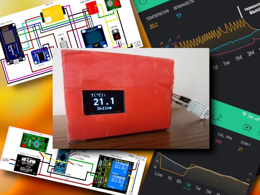
A commercially available wireless room thermostat works in the autonomous heating system of my apartment. Of course, the thermostat was purchased to save gas and make things more comfortable.
The thing is very useful, but, in my opinion, somewhat outdated. It was decided to assemble something similar to the purchased thermostat, after adding more convenient settings and an Internet connection to the thermostat circuit.
AcquaintanceFeatures and characteristics:
- Communication between the thermostat nodes is carried out over the air at radio frequency.
- During the day, the thermostat maintains three set temperature values constant.
- Thermostat settings (work program, air boundary parameters, etc.) are set remotely via Wi-Fi from a form in the browser.
- The thermostat includes an air quality monitor that measures temperature, carbon dioxide levels and air humidity.
- The thermostat is equipped with a real time clock with clock synchronization with an exact time server via the Internet.
- The thermostat is controlled from the interface of the Blynk mobile application on a smartphone. In addition, the Blynk app receives and displays temperature, CO2 and humidity measurements on a smartphone.
- The thermostat works autonomously if Wi-Fi is not available.
- The thermostat sends messages to e-mail if the temperature, CO2 content or air humidity are outside the threshold values.
- In the thermostat, in addition to temperature, it is possible to maintain other measured air parameters within the specified limits - this is humidity and carbon dioxide content.
- The device can be used to organize automatic humidification, forced ventilation or air conditioning.
- At the end of the heating season, the thermostat does not need to be hidden: the air quality monitor will remain in operation. The clock will run, and messages about temperature, humidity and carbon dioxide content will be sent to e-mail.
The thermostat consists of two devices. The first device generates and transmits to the second device a control signal for a heating device or heating system, let's call this device an analyzer. The second device receives the signal, decodes it and controls the heat source - let it be a contactor. The connection between the analyzer and the contactor is wireless, at radio frequency.
To assemble the device, you will need the components listed below. The estimated cost of components at the prices of the AliExpress is $50.
analyzer
- Wifi board NodeMCU CP2102 ESP8266
- Temperature and humidity sensor DHT22
- CO2 sensor MH Z-19
- Clock RTC DS3231
- Screen OLED LCD blue 0.96" I2C 128x64
- RF module 433MHz, transmitter (set price: transmitter, receiver)
- 4-channel logic level converter 3.3V-5V (Logical Layer Converter)
- Voltage stabilizer LM7805
- Adapter AC100-240V 50/60Hz DC12V 2A
- Breadboard (fiberglass), contacts, etc.
contactor
- Arduino Pro Mini 5V Module
- RF module 433MHz (receiver)
- 2-channel relay module
- AC-DC adapter HLK-PM01
- Breadboard (fiberglass), contacts, etc.
Both devices are assembled on fiberglass breadboards. Installation - hinged (volumetric). This approach has a number of advantages: the components are easily dismantled, the installation is easily changed to a new version of the sketch, and, finally, in a home-made case, it is not visible how it was made.
The antennas at the transmitter and receiver are a 17.3 cm long wire. The increased transmitter power and the simplest antennas provide reliable communication within the apartment.
AnalyzerThe brain of the analyzer is the ESP8266 controller on the NodeMCU CP2102 module board. It receives signals from sensors and generates control signals for the transmitter and screen.
When installing the DHT22 sensor on the board, the measured temperature is 1.5…2°C higher than the real one (even without a case!). Therefore, you should place the temperature sensor away from the high heat dissipating elements LM7805 and NodeMCU CP2102. In addition, it would be nice to install the LM7805 voltage regulator on a heatsink, and it is definitely necessary to ensure good air convection in the case to lower the temperature and reduce temperature measurement errors. Another option to get rid of the error is to move the DHT22 sensor outside the case volume - this option is simpler and I chose it.
There are a lot of complaints on the Internet about the low accuracy of measuring the humidity of the DHT22 sensor. Today there is an alternative: more modern temperature and humidity sensors HTU21D, Si7021, SHT21.
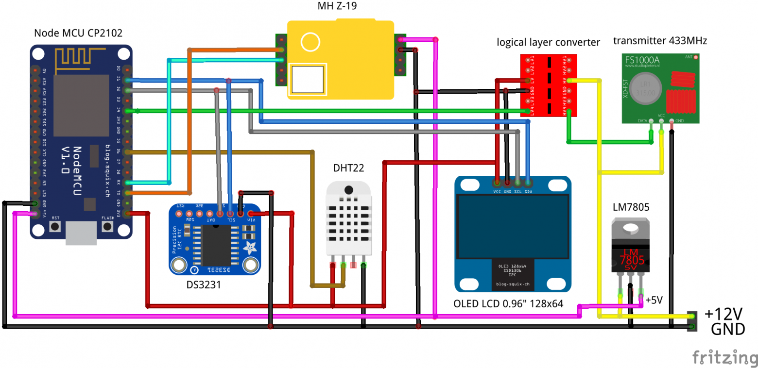
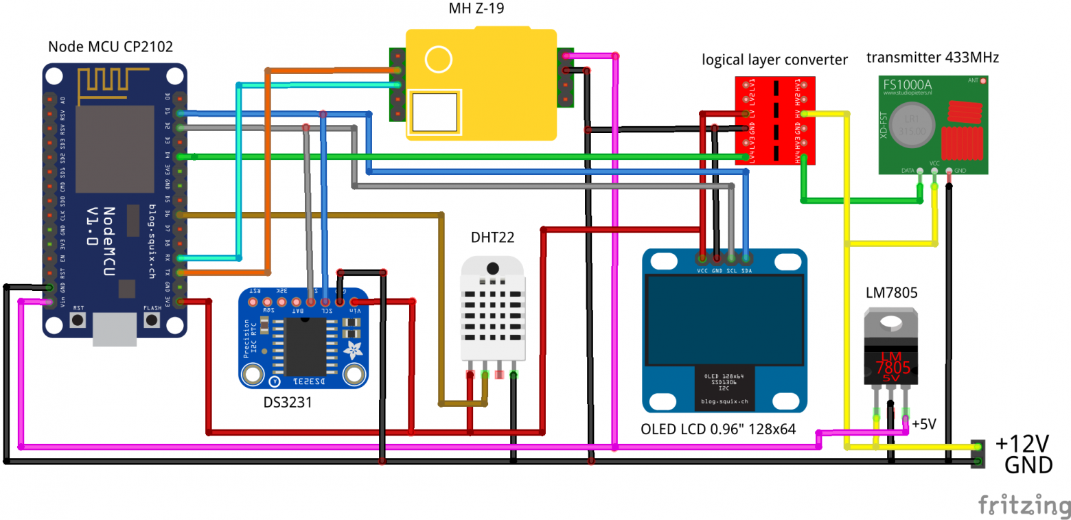
The analyzer is supplied with a constant voltage of 12V from the AC/DC adapter. Next, the LM7805 DC voltage regulator generates a voltage of 5V. The transmitter supply voltage is 12V. When testing the device, when the analyzer and the contactor are located side by side on the desktop, the analyzer can be powered from the USB port of the computer by applying voltage to the NodeMCU CP2102 module using a standard USB-microUSB cable. The supply voltage of NodeMCU CP2102 and MH Z-19 is 5V, the power supply of the remaining nodes of the circuit (3.3V) forms the stabilizer of the NodeMCU CP2102 module.
The temperature and humidity sensor DHT22 is connected to the D6 pin of the NodeMCU CP2102 module. DC3231 clock and 0.96" display are connected to ESP8266 (on NodeMCU CP2102 module) via two-wire I2C interface, and Tx, Rx pins of CO2 content sensor MH Z-19 are connected to Rx, Tx pins of ESP8266 respectively. The transmitter signal comes from NodeMCU CP2102 through converter logic levels, which converts the signal from the NodeMCU CP2102 with an amplitude of about 3.3V into a signal whose amplitude is close to the transmitter supply voltage of 12V.
If you use a battery instead of a rechargeable battery in the clock module, be sure to break the battery charging circuit, otherwise the battery will swell after a few weeks of operation under voltage. With self-powered watch, the accuracy of 2 seconds / year is guaranteed to you.
If at least one of the air parameters goes beyond the programmed thresholds, then every half hour the device sends an e-mail with the following content:
This message was generated automatically by air quality monitor 7687859. One or more room air parameters (temperature, humidity or carbon dioxide content) are outside the specified limit values. === Temperature: 20.40°C === Humidity: 49% === Carbon dioxide content: 617 ppm === Analyze the information! === Date: 11:35 09/01/***
The contactor is controlled by the Arduino Pro Mini module. It receives a signal from the RF receiver and generates signals for exceeding the threshold values of air parameters.
The supply voltage of all 5V contactor units comes from the AC/DC adapter HLK-PM01.
Connect the open relay contacts (red and yellow wires in the diagram) to open the heater power circuit.
The signals from the controller outputs 6 (h > Hmin), 5 (co2 > CO2max), 3 (t > Tmax) can be used to organize automatic humidification, forced ventilation or air conditioning. The advantage is that there is no need to lay a cable to transmit the control signal from the sensor to a specific system - it is enough to place a contactor near one end of the power or system control wire.
It's time to turn on the thermostat.
Step #1
Let's turn on the analyzer first.
First you need to be patient and, without doing anything, wait 3 minutes. The thermostat will automatically switch to offline mode - without a Wi-Fi connection to your home network and the Internet. After 3 minutes, the measured air parameters will be displayed on the analyzer screen in three lines.
The first two lines on the screen do not require comments. The third line contains the thermostat operation mode (Offline, Online or OffBlynk) and information about going beyond the set threshold values of air parameters. For example, Offline CO2>1000 - the thermostat is offline and the measured CO2 content is above the set threshold of 1000 ppm.
The clock in offline mode will show the wrong time. They have not yet been synchronized with the exact time server, and the time zone has not been entered - this is in the next step.
In offline mode, the thermostat temperature is set to 21°C during the day. It can be changed.
Step #2
Having mastered the standalone mode, turn off and then turn on the analyzer's AC/DC adapter. A familiar message will appear on the screen, which you have gotten used to in three minutes of waiting for offline mode.
The am-5108 access point is raised in the device. Let's find this point in the list of available networks and connect to it, the password is on the screen. Then open http://192.168.4.1 in your browser.
Click the Configure WiFi (No Scan) button. The page with the thermostat settings form will open:
The same form with empty fields and comments:
We will indicate in the form the name and password of our home network, the BLynk identification key, and email. Let's change the default time zone, time (hours) and temperature for time points, as well as threshold values for temperature, humidity and CO2 content.
The day is divided by two time points into three time ranges - the first: from 00:00 to point 1 (Hour 1, Minute 1), the second: from point 1 (Hour 1, Minute 1) to point 2 (Hour 2, Minute 2) and third: from point 2 (Hour 2, Minute 2) to 00 hour 00 min. There are no fields for entering minutes on the form, minutes for points 1,2 can be changed in the sketch (variables MinPoint1, MinPoint2). In each of the three time ranges, you can set your temperature control temperature - Temperature 0, Temperature 1 and Temperature 2. If you plan to keep the same temperature constant throughout the day, then it is enough to set the Temperature 0 value, and leave the fields for points 1.2 empty.
When choosing threshold values for air parameters, be guided by the indicators that I found on the Internet:
1. Comfortable temperature at night during sleep 19 ... 21 ° C, during the day 22 ... 23 ° C.
2. The optimal relative humidity in the cold season is considered to be 30 ... 45% humidity, and in the warm season 30 ... 60%. Limit maximum humidity: in winter it should not exceed 60%, and in summer - 65%.
3. The maximum level of carbon dioxide content in the premises should not exceed 1000 ppm. The recommended level for bedrooms, children's rooms is no more than 600 ppm. The mark of 1400 ppm is the limit of the permissible content of CO2 in the room. If it is higher, then the air quality is considered low.
By default, the daily temperature control program (during the day - high temperature, at night - low) is set on the assumption that during the day one of the residents is in the room, for example, working at home. The program is easy to change to fit your needs.
The e-mail field can be left blank. Then the provided opportunity to receive e-mails about the exit of air parameters beyond the threshold values will be lost. Without the Blynk key entered, it is impossible to control the thermostat and receive information about the air parameters at a distance. However, the thermostat will not “get lost” if the fields with the limit values of the air parameters remain blank, then only one function will remain behind it: temperature control.
And further. Please enter all numbers in the format of floating-point variables, then the conversion to the desired format is performed in the sketch. Exception: time points 1,2 (hour) - integer format.
After saving the settings in the ESP8266 memory (Save button), the analyzer will connect to the network and start working.
If you made a mistake or decided to change the settings, you will have to upload the sketch twice again to the ESP8266. The first time - with the factoryReset (); line uncommented in Setup and the second one with the commented one and then repeat step #2.
Step #3
Now you can turn on the contactor.
With a stable radio connection between the analyzer and the contactor, the D13 LED on the Arduino board blinks at a frequency of about 1 Hz.
If the contactor has received a command from the analyzer to turn on the heater or heating system, the normally open relay contacts will close and the corresponding LED on the relay module will light up.
If there are no problems with the "idling" of the contactor, then we connect the heating device or the electronics of the heating system. The heating device should be connected with a wire of a certain section. The specific indicator for calculating the cross section of a copper wire is 5 A / mm2.
Step #4
It's time to launch the Blynk app on your smartphone. There is a lot of information about the Blynk app on the Internet - there is no point in repeating it.
Variables for Blynk (so as not to look for them in the analyzer sketch): temperature - V1, humidity - V2, CO2 content - V3, control temperature - V4, virtual button - V10.
On my smartphone, Blynk’s interface (it can be changed) looks like this:
On the graph - the measured temperature (white), thermostating temperature (yellow), time interval - day. Variables for humidity and CO2 content are not displayed on the graph, since two additional scales severely limit the field of the graph, where the curves themselves can be considered.
The signal from the virtual THERMOSTAT button is generated only at the moment the button is pressed. When the button is pressed, the message Thermo OFF! flickers on the analyzer screen. or ThermoON! – depending on the previous state of the button. This message is relevant when testing the thermostat.
The screenshot below illustrates the process of heating a room with an area of about 5 square meters with an initial temperature of 16°C with a 2 kW/h fan heater. Here - temperature (yellow), humidity (blue) and CO2 content (red).
The jagged humidity curve synchronous with the temperature saw on the graph is another confirmation of the well-known fact that an open heating element dries the air, and the peaks on the CO2 content curve are evidence of my short-term visits to the room.
IntentionsIn the future I plan to work on improving the thermostat. Lots of tasks:
- Complement the thermostat with a temperature sensor with wireless communication to measure the temperature outside.
- Replace a pair of RF receiver-transmitter with another pair with a longer communication range at a supply voltage of not more than 3V. Ideally, I would like to develop an analyzer powered by two AA batteries during the heating season.
- Get away from manually formatting the ESP8266 memory before every thermostat change by re-uploading the sketch.
- Extend the thermostat's programmable cycle from daily to weekly and increase the number of temperature bands per day.
- Replace the monochrome screen with a color one with a higher resolution. This will allow you to show all information about the operation of the thermostat in one frame, and when the air parameters go beyond the set limits - by changing the color.
- Then deal with printed circuit boards and a presentable appearance of the thermostat.
- Thanks to the Internet connection, the functionality of the thermostat has expanded significantly. For example, sending email alerts.
- A new quality has appeared in the thermostat: it can be controlled and monitored the air parameters in the room at a distance (for example, from another continent), via the Internet.
- I am pleased with the ease with which the thermostat is programmed: you only need to fill out a form on the browser page.
- The device can be used to organize automatic humidification, forced ventilation or air conditioning.
- Now it is possible to save personal data in the thermostat's memory, as is done, for example, in routers.


_qDT2N5Sg1I.jpg?auto=compress%2Cformat&w=48&h=48&fit=fill&bg=ffffff)


_3u05Tpwasz.png?auto=compress%2Cformat&w=40&h=40&fit=fillmax&bg=fff&dpr=2)


Comments
Please log in or sign up to comment.