


Hardware components | ||||||
 |
| × | 1 | |||
| × | 1 | ||||
| × | 1 | ||||
| × | 1 | ||||
 |
| × | 1 | |||
| × | 1 | ||||
Software apps and online services | ||||||
 |
| |||||
| ||||||
For hospitals, it would be good to have an IoT logging device that can measure the distance between individuals.and also collect exposure time information. This would ease the effort of contact tracing during a health crisis like the Covid19 pandemic.
How does it work?I am using infrared sensors and ultrasonic sensors to precisely measure distance between individuals. The sensors identify the individuals and measure the duration of exposure.
A simultaneous ping of infrared light and ultrasound is used to measure distance accurately. The infrared light ping is used to start measuring distance, by timing the delay for the ultrasonic ping to arrive at another badge. The Arduino Nano 33 BLE will use the sensors and decode infrared serial data to identify the badges and send exposure data to the cloud.
At 20 degrees C, the speed of sound is about 343 meters per second. So 1 millisecond delay corresponds to a distance of 0.343 meter.
Keeping things simple using 80000 bits per second
The ultrasonic transducer works with a frequency of 40 kHz. Sending a stream of uppercase U characters serially at 8 bits, with no parity at 80000 bits per second, creates a nice 40 kHz signal. After sending a few U characters a badge identification number is sent. The exact same signal is used to make the ultrasonic transducer sound and light up the infrared led.
Helpful Tips
- Use a reasonably fast infrared sensor
- Use a JFET input op amp with the infrared sensor and ultrasound microphone
- Use this analog comparator circuit to extract the digital signals for use by the Arduino.
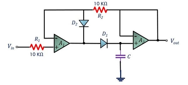
Description of Analog Comparator:
D1 is a fast photodetector diode. The resistance value of R4 sets the sensitivity of the detector. More resistance creates more sensitivity. But increasing the resistance also slows the response of the photodetector diode, there is a balance between these two design goals that needs to be reached. The LF353 op amp has JFET inputs and is ideal for use with the photodetector and the ultrasonic microphone.
The LM339 analog comparator takes the photodiode amplified signal and turns into a digital logic level signal for the Arduino. Capacitor C3 averages the photodiode signal and tracks the average over time. The value of resistor R3 adjusts how quickly the average can adjust to the photodiode signal. This permits the signal to vary in strength while still producing a good logic level output signal for the Arduino.
Adding BLE wireless data communications
There is a need to download the collected data about exposure times and distances. I am using BLE to transmit wireless data since it uses less battery power and is inexpensive, The Arduino Nano 33 BLE board is an ideal platform for developing this application.
I have included my first step in blending a Arduino Nano sketch and the Arduino Nano 33 BLE ButtonLED example code sketch. The blended sketch is called BadgeButtonLED.
For my development work I am using a Raspberry Pi 4 as my BLE central device. I am using the Bluez bluetooth stack for collecting data from badges.
Below is a link on how to use gatttool interactively and within a script.
http://www.humbug.in/2014/using-gatttool-manualnon-interactive-mode-read-ble-devices/

Comments
Please log in or sign up to comment.