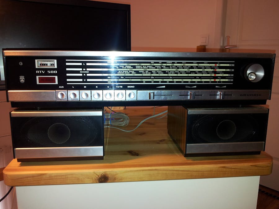
The story of this project started when I opened an old box from my attic. Inside, I found my old seventies radio that I used to listen to when I was a teenager. I remember the particular way to search for AM or FM radio stations : the big knob to turn and move the red cursor behind the illuminated front face, the red light that comes on when stereo sound reached home ! After a quick test, the receiver didn't made any sound apart from a "shhhhhhhhhh". Thus, I decided to revive it.
But I wanted to keep it the way it was working thirty years ago. No changes, original buttons, original features. Just integrating a Raspberry Pi inside, wired to the original switches, lights, buttons and amplifier.
Here is how it works ...
Hardware frameMore details about the original GRUNDIG RTV500 receiver can be found on the radiomuseum site.
This picture shows you the modified hardware frame :
On the right side, power supplies. On the left side, the new digital variable capacitor.
On the main board, HF electronics system didn't work anymore. Following the electronic plan, I removed all the related components. I kept the audio amplifier and I connected it to the Raspberry Pi audio output via a jack. The Raspberry Pi and the externals elements were installed on a white plastic board.
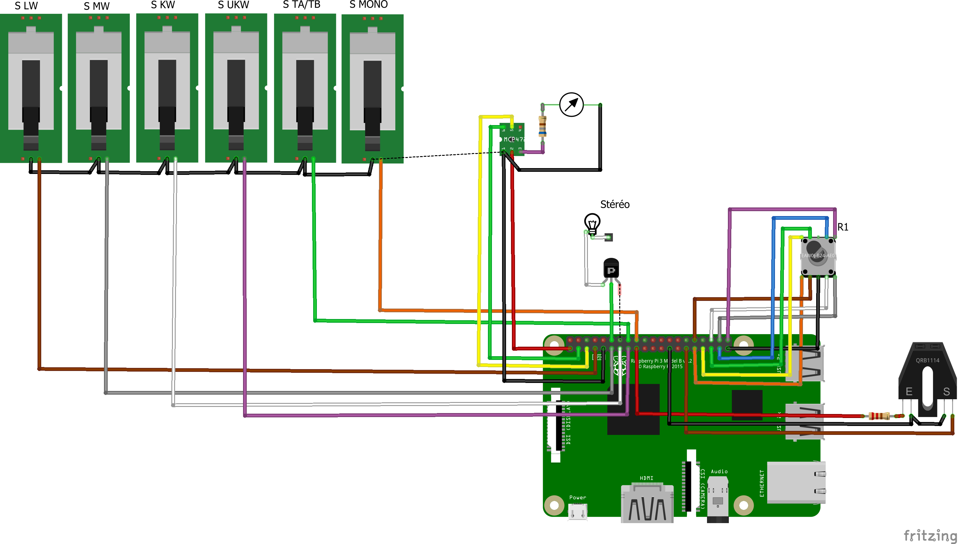
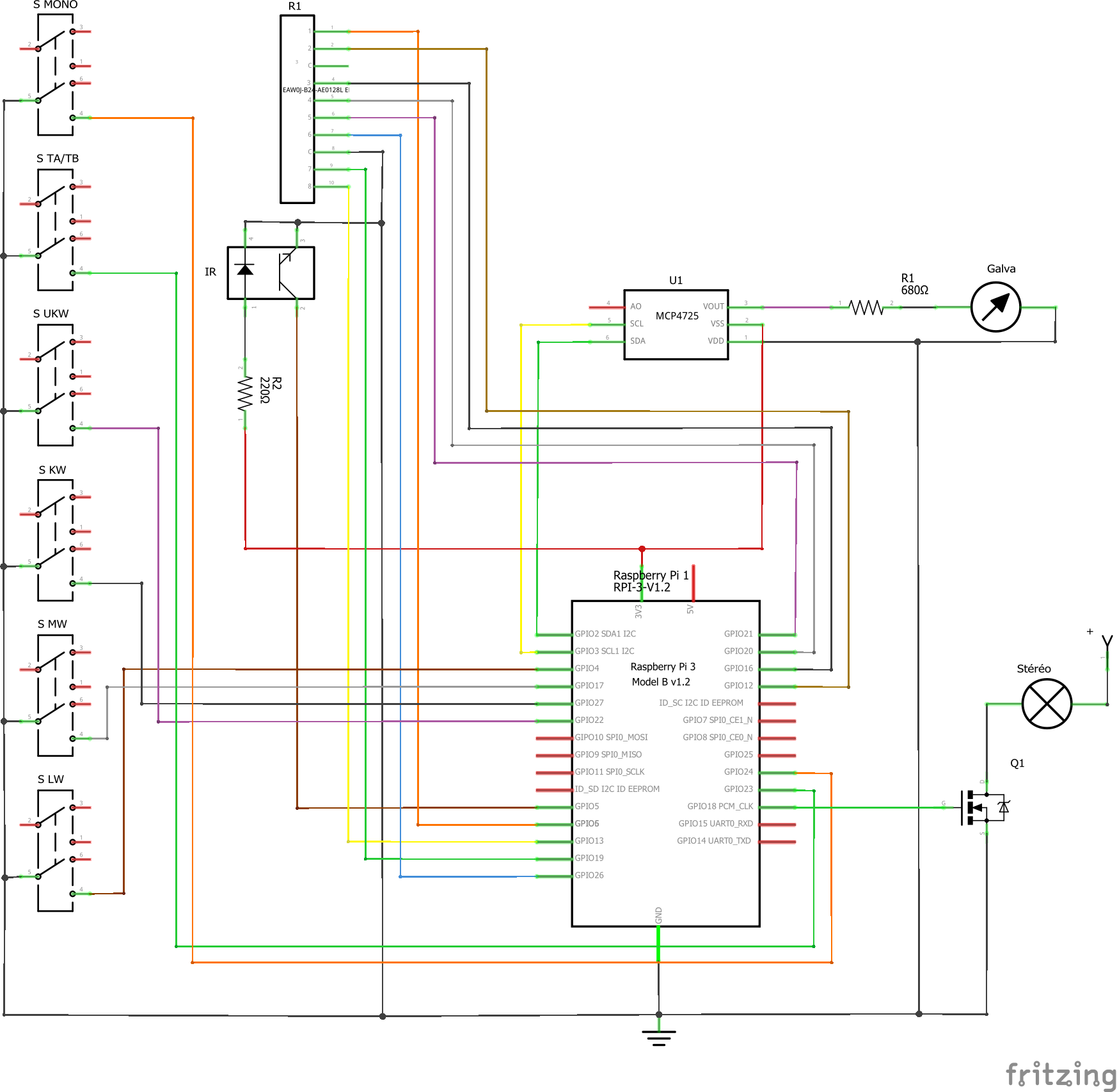
Each front panel selector was connected to one GPIO pull-up input pin to tell the Pi which button is pressed. This took 6 GPIO pins.
Knob positionI needed a rotating encoder to get the tune position from the old variable capacitor. I conserved the frame including two axis. The first one rotates to 540 degrees (one rotation and a half), and the other one to 180 with up and down stop mechanism. For more resolution, I decided to use the 540 axis for the rotating encoder, and I added an infrared sensor to the second axis. 9 GPIO pull-up input pins were used, 8 for the rotating encoder (refer at the encoder data sheet below to understand why 8 bits is needed to get only 128 values), and 1 for the infrared sensor. This sensor acts as a MSB bit to detect when the first axis is between 360 and 540 degrees. This system allows to get a position value between approximately 0 and 200 with a full travel of the front cursor (about 270mm). The common rotating encoder is wired to ground. The infrared emitter led draws power from a 3.3V Raspberry Pi pin.
Stereo LightThe stereo light was connected to a GPIO output through a MOSFET. This MOSFET allows to drive a real bulb light powered by 7V - 150mA from a 3.3V GPIO output.
Signal strengthThe signal strength indicator is a galvanometer. I used a MCP4725 which is a DAC converter connected to the I²C bus. It generates the voltage to move the hand from the dial. Because the DAC works between 0 and 3.3V and the galvanometer has full scale at 0.5V, I added a 680 ohm resistor to limit the voltage.
The Raspberry Pi draws power from an official Raspberry Pi 3 compliant power supply that is always on, even if the front selector is in the AUS state (OFF in German). This avoids Windows boot time latency at startup (about 40s) and hard power off without proper system shutdown.
The original power circuit was broken, of course it came from the zener diode of the regulator circuit ! Replacing this diode was too expensive and too complex (about 20€ and 8000km, not very CO2 compliant !). I decided to adapt a modern LM317 regulator to generate the correct voltage that the original board needs, and remove the transistor and the zener.
A C# UWP headed application under Windows Iot Core. For software development, I connected an HDMI screen to see what happens on the Raspberry Pi board. But in normal operation, no screen needs to be connected. However, I am planning to use the Windows Iot Remote Client app to take remote control of the Raspberry Pi from any Windows 10 device, to sometimes visualize the WPF interface that shows information and states only.
If you download the VS2015 solution below, you will find 2 projects and 3 libraries. The RTV500Pi project is the full functional package that is running on my RTV500Pi radio. All external hardware components are required to run this project. You can run this project on your Raspberry Pi, but nothing will appear because the front selector switches and the tune button are missing. However, I made a second project named RadioDemo that can be built and executed on any Windows 10 device with WPF buttons and slidebar to simulate on your computer the hardware components. I also use this project to test the general classes on my computer instead of always remotely execute it on the Raspberry Pi.
Audio producingThe software is in charge of simulating the sound of the old radio when turning the knob for searching stations. This behavior is realized by using two MediaPlayer controls : the first one is a MediaElement playing the webradio stream, the second one is the BackgroudMediaPlayer instance playing continuously a pink-noise wave file. The volume of this one is adapted to produce the mixed sound of radio and pink-noise when the cursor goes near the correct frequency. In fact, this continuous background sound avoid crackles each time you start playing a stream or something else (known issue from the audio card of the Pi).
Radio station programmingEach of LW, MW, KW and UKW band can be programmed with a set of radio stations by calling AddStation()
method of the Radio
object, before initialize it in the MainPage.Page_Loaded()
event method.
public RadioStation AddStation(string name, WaveBand band, byte frequency, string address, bool stereo, byte displayRow, double[] ReceipValues)
Here is the meaning of each parameter :
name: the name of the radio station you want to add. This is only used to display it on the WPF interface and to easily identify it in the source code.
band: the wave band at which you want your new radio station to appear (LW, MW, KW or UKW).
frequency: the central frequency at which you want the radio station to appear in the wave band. This parameter is abytenumber representing the knob position between 0 and 200.
address: the url of the webradio stream to play.
stereo: If true, the stereo light will be turned on when this radio is playing.
displayRow: on the WPF interface, the station names are displayed on multiple rows. By default, this value must be 0, but if there is not enough space to fully display the name, you can increment this number to put your station name on the next row.
ReceipValues: By default, you will pass an array of these values :
new double[] { 1, 2, 3, 4, 3, 2, 1 }
These values are used to simulate the tuning process by mixing pink-noise and radio stream, and driving signal strength galvanometer (this is why values must be between 0 and 5). The max value in this array matches with the central frequency
parameter. A value greater than 4 cuts off the background pink-noise volume. So if you want to clearly hear your station, put at least a 4 or greater value. On the other hand, if you want to simulate a far away station, let values lower than 4.
In the source code of the Radio
class, you will find the FM radio set of Paris on UKW band represented by the static AddParisRadios()
method, and the four national AM stations from France on LW band represented by the static AddFrenchLWRadios()
method. Theses methods might be useful to help you to understand how the AddStation()
method works.
The TA/TB button, normally used to get audio from a TAPE A or TAPE B external source, enables a MP3 player. At start up, the Music Library is scanned to get all audio files. Theses files build a MediaPlaybackList
passed to a MediaElement
object.
The radio is now installed in the living room, playing background music or news. It looks and works like an old radio. No need to read a manual book to know how to use it. Everyone knows how to use this simple and intuitive radio !
The hardware and audio are fully functional. I am currently working on further improvements on the UI interface. I already plan to use the standalone MONO button like a Bluetooth switch, that allows to play music from any audio Bluetooth-linked device. This need the Bluetooth profiles to be supported by Windows IoT Core.
Stay tuned for new versions of the software !


Comments
Please log in or sign up to comment.