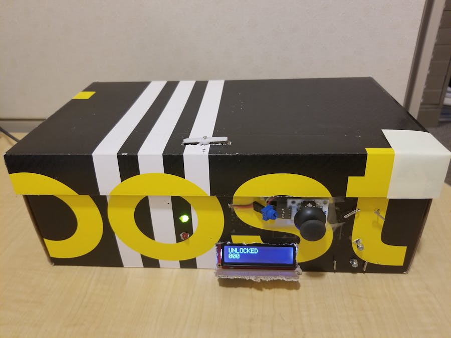
Keeping valuables safe and locked away is important to everyone. While you can have a manual safe, why not build your own safe box and add some smarts to it? Using an Arduino, a servo, joystick and an LCD screen, you can make the electronics for a combination lock safe.
This diagram shows the flow of data for the safe.
Sensorsa. A joystick that controls the digits displayed on LCD screen.
b. Two push buttons that are used to enter and set a new password.
c. A potentiometer that controls the LCD screen’s brightness.
Processinga. Simulink and Stateflow algorithm that processes the data coming into the Arduino MEGA and sends appropriate outputs to the Actuators.
Actuatorsa. An LCD that displays the mode and current combination
b. LEDs that display if the attempted password is correct (green) or incorrect (red)
c. The servo motor unlocks the safe when the password is right.
Sensor CircuitJoystick: This one requires 5V and two pins that relay the XY axis information. The joystick consists of two perpendicular potentiometers that vary the voltage as the stick is pushed up/down/right/left. Since the output of the joystick is an analog value of voltage, read in at pins A2 and A3. We need to threshold this signal to change this to a digital value for the direction. More on that later.
Pushbuttons: The pushbuttons need 3.3V power and their status are read at pins 38 and 39 respectively.
Actuator circuitLCD: The LCD screen is a 16 x 2-character, 16 pin, backlit screen. I used six DIGITAL pins to run the screen and the connections are shown above.
LED and Servo: I am using a transistor (BJT) to control the power to the LED. I did not want to wire the LED directly to the Arduino because the voltage is not always exact. The servo is controlled with 5V and a PWM pin.
Software: Simulink is a block diagram environment to design dynamic systems and develop complex models and algorithms. This proved very useful as I could focus more on the parameters, rather than worrying about code syntax. It also provides a visual framework for modeling physical systems which I really enjoyed using. I also used Simulink to deploy the code to an Arduino and have it run standalone. Here is the top layer of the model:
Simulink’s External Mode allowed me to plot the input data from the Joystick. It also helped me tune the minimum and maximum threshold on that signal. Using this analog to digital conversion, the algorithm can now understand if the Joystick moved up, down, left or right. A sample of this is shown below: the first image shows what happened when I set the threshold too high; no movements were recognized, as opposed to the second image with lower thresholds.
Displays and dashboard blocks were useful for debugging the model without the hardware, or when some hardware was not working properly.
StateflowStateflow is a useful tool for creating state machines. Each state has actions and exit conditions associated with it. A major benefit to using Stateflow is that the algorithm logic is isolated from inputs and outputs, so if I wanted to deploy this model on another board, but the inputs were different, I could still save the bulk of the model because the state logic is reusable. The same is true for all non-Input/Output blocks. In external mode, you can view which state you are in in the Stateflow diagram, allowing you to trace your state logic easily. Here is the state logic for the safe. The Arduino inputs are used to change the state.
Device Driver Blocks:
The LCD block is not part of the Arduino Simulink support package, but I wrote a simple custom device driver block for it using existing Arduino libraries. This LCD block takes in uint8 ASCII values of the strings that I wish to print, and displays them. All the files for this LCD library are here. Here is a useful video link if you want to create your own MATLAB system block.


_wzec989qrF.jpg?auto=compress%2Cformat&w=48&h=48&fit=fill&bg=ffffff)


_3u05Tpwasz.png?auto=compress%2Cformat&w=40&h=40&fit=fillmax&bg=fff&dpr=2)
Comments
Please log in or sign up to comment.