One the biggest challenges in the Internet-of-Things (IoT) is power. Some IoT devices are kept near power outlets, while others must run off a battery or other non-rechargeable energy source. Devices that run on a battery must be carefully designed and implemented to reduce power consumption as much as possible. While small microcontrollers (MCUs) can consume very little power, developing applications on them is more challenging than on a Single Board Computer (SBC), such as a Raspberry Pi® or a similar Unix-based SBC. SBCs are an easy platform to develop on with support for a wide array of programming languages and libraries, but as a tradeoff, they consume a lot more power than a small MCU, even when shut down.
Note: “Raspberry Pi” and the Raspberry Pi logo are registered trademarks of the Raspberry Pi Foundation.
To increase battery life, we developed a simple power controller using a small 8-bit MCU. The PIC16F15245 MCU is designed to smartly control the power to the Raspberry Pi to reduce the amount of power consumed when the Pi is turned off. As an example of a potential use case, if the Pi was only used to send data once an hour, the remaining time spent idling will waste the battery. If the small MCU is in control of powering on and off the SBC when transmissions are needed, the total power consumption is much lower.
This block diagram shows the theory of operation. An MIC4684 buck regulator reduces the 12V input voltage to an appropriate level for the Raspberry Pi. To provide a stable source of power for the 8-bit MCU, a small MCP1702T Linear Drop Out (LDO) Regulator is also added.
The MCU has two interfaces setup in this example. One is an I2C bus for the Pi to communicate with the MCU. This communication will be discussed in more detail in the “Serial Control” section of this post. The other communication interface is an external trigger. If a trigger occurs, then the MCU will immediately restore power to the Pi.
Serial ControlFor serial control, the Pi communicates with the MCU over I2C. The I2C commands to the MCU take the format of:
“S” + 6 digits for the number of seconds to wait
For example: “S007200” is interpreted as Sleep (Power Off) for 7200 seconds.
More complex control schemes can be implemented by modifying the MCU’s firmware as needed. After receiving a command, the MCU waits 30 seconds to give the Pi time to fully shutdown, then it disables the power regulator for the device.
Power SavingsDisclaimer: Power consumption varies based on the input voltage (12V in this case) and the output load. Your results will vary.
- Power Usage in Software Shutdown: 1.5W
- Power Usage with the Control Board (fully shutdown): 0.028W [28mW]
As shown by these measurements, there is a power savings of over 53x by using the MCU control board.
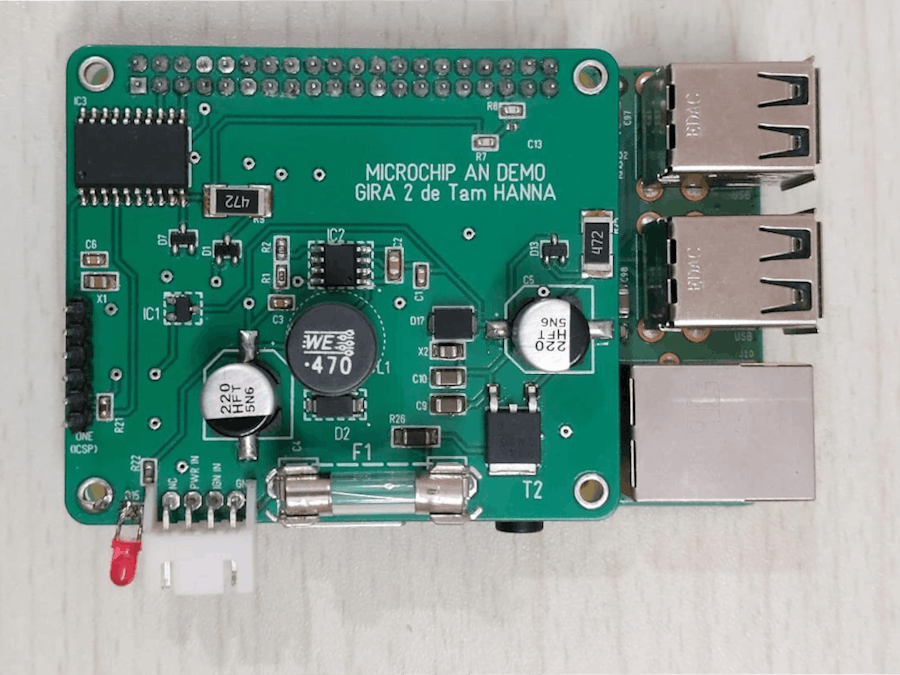
Circuit DesignThis circuit has 3 parts, corresponding to the 3 Integrated Circuits on the PCB.
The first part (IC1) implements the LDO for the PIC16F15245. The MCP1702 converts the 12V input to a 3.3V output. Capacitors X1 and X2 are used for regulator stability.
The second part (IC2) implements the MIC4684 Buck Regulator. This regulator converts the 12V input into 5V for the Pi. The enable input of this regulator is used to turn off the power when requested.
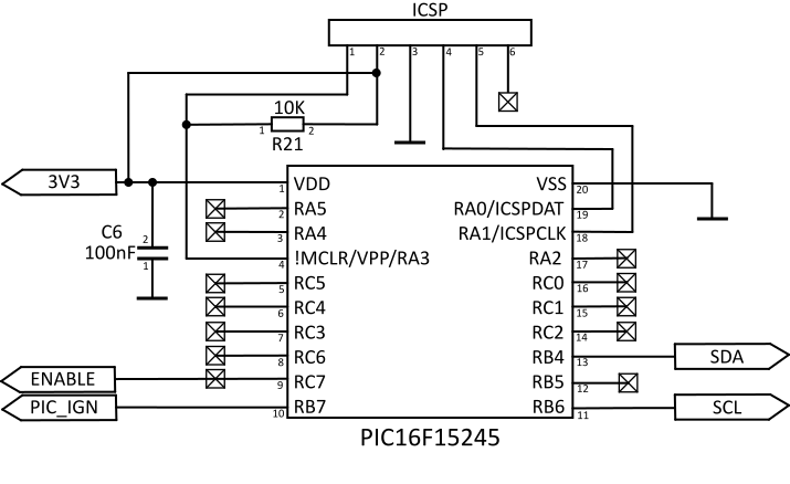
The final part (IC3) is the microcontroller itself. An In-Circuit Serial Programming (ICSP) header is included for a programmer, such as a PICKIT 4, to be attached to the device. Alternatively, if the MCU was pre-programmed, then this header could be omitted.
The circuit was built on a PCB that sits on-top of the Raspberry Pi. To keep the board stable, spacers were 3D printed in OpenSCAD (https://openscad.org/index.html). OpenSCAD is an open-source tool that generates 3D models from script files.
(Tam Hanna, one of the authors of this app note, has a book on OpenSCAD, available here: https://www.amazon.com/Technical-Modeling-OpenSCAD-Tam-Hanna/dp/1907920994/)
Possible Design ExpansionsThere are many ways to tweak and adjust this example to fit the needs of the application. One option would be to add-on an external Real-Time Clock (RTC) to schedule power-on and power-off times, rather than using a duration of time to remain in sleep. This clock could also be synchronized by the Pi to set an accurate time or could be used to provide time data to the Pi, depending on the use.
Another possibility would be to integrate a power consumption monitor, such as an PAC1952. This would allow for the MCU to keep track of the amount of current being consumed to provide an estimate of battery life remaining, if powered from a battery.
ConclusionThis application shows a simple, but powerful way to save power when using high performance SBCs in battery powered applications. Since microcontrollers are software-based devices, they make for excellent starting points for tweaking and developing designs to fit the design needs. For more information about this application, please consult App Note AN4121.
Usha Ganesh (Microchip), Tam Hanna (Tamoggemon Holding k.s.)


Comments
Please log in or sign up to comment.