Inosensor ES Devkit is a development kit for ST company's sub GHz band transceiver S2-LP based Sigfox module IFS-M01.
It is a model equipped with buttons and contacts x2, so if you want to try Sigfox for the time being, you can send Sigfox message triggered by button or contact input if you prepare only dry batteries. Also, for engineers, it can be developed with ST SDK.
Power meter module [INA226PRC]
The current consumption is measured using Strawberry Linux's INA226PRC I2C digital current/voltage/power meter module.
The specifications of INA226PRC are as follows.
Since it is possible to measure up to 81W, I think it is suitable for embedded sensor systems. (The standby current is not possible...)
As shown in the picture below, in addition to the module board, terminal block x2 and 2 types of connectors are attached, so select the connector that suits your environment and solder it.
Also, in order to set the I2C address, when the address is set to 0b1000000x as shown in the figure on the right below, it seems that it is necessary to drop the ground at G by soldering.
Wiring between INA226PRC, Sigfox module and M5Stack
This time, I want to measure the current consumption of the Sigfox module, so I will use 3 IC clips and a lead wire for shortcut, and wire them as shown in the figure below.
The wiring of the INA226 module seems to have a high side connection where the ground potential is common and a low side connection where the power supply potential is common, but the recommended high side connection was used.By the way, the terminal side is as shown in the picture below.
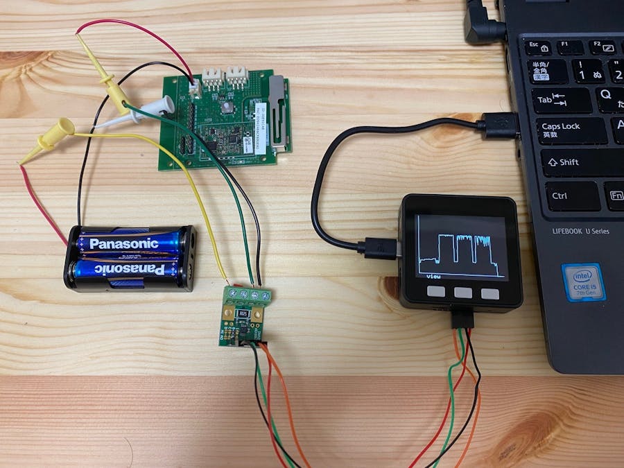
The completed wiring looks like the picture below. (Current value graph is already displayed on M5Stack, but don't worry about it)
Current/voltage measurement program
M5Stack and INA226RPC communicate with I2C to measure the current value and the voltage value, so it is possible by using the Wire library (include Wire.h). Moreover, the program that samples the current and voltage value from INA226 in millisecond units and displays it on the screen has been uploaded to GitHub by Takehiko Shimojima, so I decided to divert it.
it's here.
I didn't have an SD card, so I commented out the writing part of the SD card and changed it to send the result by Serial. The sample sketch is as follows, so please download and use other necessary files from the GitHub repository.
Calculate power consumption
The result of time change of current consumption when sending data with Sigfox is shown in the figure below.
If you look at the current consumption graph above, you can see that the message has been sent three times. The current consumption during message transmission is about 20mA (Is that a little lower than the nominal value?), and it is said that the current consumption during Wi-Fi data transmission is 100-200mA, so LPWA has low power consumption. As you can see from the results,
Furthermore, let's consider power consumption and batteries.
The current consumption per communication (3 messages) is 2.08[s] when the transmission time of 1 message is
20[mA] x 2.08[s] ÷ 3600[s/h] = 0.011556[mAh]
Assuming that you communicate once an hour,
0.11556[mAh] x 24[h/day] ÷ 1[h] = 0.277333[mAh/day]
Is the current consumption per day.
Assuming a device with no sensor (for example, only button notification), if the standby current is 1 μA
1[μA] x 3600[s/h] ÷ 3600[s/h] x 24[h/day] = 0.024[mAh/day]
The current consumption per day is 0.277333 + 0.024 ≈ 0.3 [mAh/day].
If you want to operate the battery for 2 years, you need to prepare a battery with a capacity of 0.3[mAh/day] x 365[day] * 2[years] ≈ 220[mAh].
However, from here on, it's the battery shop's specialty. The optimum battery should be selected in consideration of the operating environment, self-discharge characteristics, safety margin, etc.
What do you think?
Once again, I felt that LPWA (Sigfox) has low power consumption, and at the same time, I think that this combination will allow you to easily measure the power consumption of your terminal or module.
Please try it.
ghibi


Comments
Please log in or sign up to comment.