


Hardware components | ||||||
 |
| × | 1 | |||
_ztBMuBhMHo.jpg?auto=compress%2Cformat&w=48&h=48&fit=fill&bg=ffffff) |
| × | 2 | |||
| × | 1 | ||||
| × | 3 | ||||
| × | 3 | ||||
| × | 2 | ||||
Software apps and online services | ||||||
 |
| |||||
Hand tools and fabrication machines | ||||||
 |
| |||||
 |
| |||||
 |
| |||||
- Arduino Uno & Due
- GPS module
- RF Communication with LoRa modules
This project has not been finished yet. We give you insights in how far we got. We don't provide code as we used a lot of code examples from the internet. However, we will provide the links.
Three important parts of the project are:
- Ground Control: Lots of buttons that start and stop / open and close parts of the rocket. (Valves, ignition, sensors,...). Sends instructions to launch pad and rocket, plus receives status updates from both.
- Launch Pad: The part, that stays on the ground. Including a valve which is used for safety reasons. Gets instructions from ground control, sends the status back to inform about errors and tell, whether instructions were executed.
- Rocket: The electronics in the rocket, that will actually fly, involving one valve. Gets instructions from ground control and sends status, as well as data during the flight to the ground control (height, pressure, temperature, location, acceleration,...)
You don't need to choose the exact components from the list. A cheap version of Arduino will do the same job. Make sure to use a leagal frequency for RF modules (like LoRa).
Step 2: Let's get started! Set up the Arduino IDEAn IDE (Integrated development environment) is the software where you code and upload the code to the board, you can download it on the arduino page https://www.arduino.cc/en/main/software (download, not code online).
Include libraries via: Sketch > include library > add zip
ConnectArduino. You need to put in COMx e.g. COM4 at Tools > Port, plus actually connect the cable from the Arduino to your laptop. Arduino Due: use a micro usb cable - there are some cables that don't work, it needs to be a data cable, not just for power. Plus there are two micro usb ports on the board (don't use the debugging one).
Board. You might need to to install Arduino Due first. Choose it via Tools > Board.
Console print. If you want to see data from the Arduino on your computer you can use the most right button in arduino ide (where you write the code). It looks like a magnifier glass and opens the console. You can print onto the console via
Serial.print("This will be printed on your console");in your arduino code. Don’t forget to set baud rate to 9600 in both, the console and the setup() code:
Serial.begin(9600);Note: your board needs to be connected to the laptop to see the output of the serial print.
Step 3: Where are you? Location with GNSS - GPS (USA)/Galileo (Europe)/GLONASS (Russia)/Beidou (China)Module. Any GNSS (mostly known version is GPS) module is fine. It doesn't need to be expensive. Ublox is good and it should have an antenna. (It is this white/metal square with a yellow/orange border). Search for gy neo buy. You are quite safe, if there is the Ublox logo somewhere on it (red u).
Info. The first module we have been working on was the GPS module which goes onto the rocket. We were using the global navigation satellite system (GNSS) from America (GPS), but any other will do, too. Very important: For the first time you connect the module (or if you moved it for a couple of kilometers), you will think that your module is not working for minutes up to hours! Leave the module outside, connected to power and let it search for the satellites. It works best with a straight view to the sky - so no clouds. Give it maybe up to 2 hours, If your module has a micro USB port, you can also connect it to your laptop and use a software like https://www.u-blox.com/en/product/u-center to see visualised what satellites are used. Figure out more by searching for: TTFF (Time to first fix), cold start, warm start and hot start.
Pins. RX, TX, VCC, GND, (no need to use PPS)
Library. There are multiple libraries - make sure you chose one that is compatible to your Arduino board:
- NeoGPS: https://github.com/SlashDevin/NeoGPS (the one we chose)
- TinyGPS: https://github.com/mikalhart/TinyGPS (TinyGPS++ is the newer version)
- TinyGPS++: https://github.com/mikalhart/TinyGPSPlus
Code. Within the NeoGPS library, there are lots of code examples. We used this one: https://github.com/SlashDevin/NeoGPS/blob/master/examples/NMEAloc/NMEAloc.ino and adapted it. Make sure, the baudrate of your GPS module matches the baudrate in your code, most likely 6900.
gpsPort.begin(9600);Make sure, you adapt the pins of the example, so they match the ones you connected the module to your port.
Search. Search for "GPS - NMEA sentence information" for more information about the data received from a GPS module. E.g. http://aprs.gids.nl/nmea/
Step 4: Are you listening? RF communication with LoRaModule. 3 times the Adafruit RFM95W LoRa Radio Transceiver Breakout - 868 or 915 MHz - RadioFruit There is an amazing tutorial for it: https://learn.adafruit.com/adafruit-rfm69hcw-and-rfm96-rfm95-rfm98-lora-packet-padio-breakouts An alternative is the 434 MHz version.
Frequency. Very important! You need to use a frequency that is legal in your country! Search for ISM band. 868 (SRD860) and 433/434 (LPD433) should be fine in Europe, 915 (33-centimeter band) is for America.
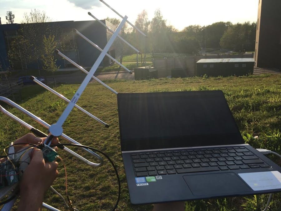
Antenna. You need an antenna for this module and therefore an adapta. Use the same frequency as your module. We just choose literally any. Sometimes a wire in a length matching your frequency is enough, depending on the distance you want to achieve. With a wire we managed over 300 meters (no straight line of sight).
Pins. VIN, GND, EN, SCK, MISO, MOSI, CS, RST
Arduino Uno:
- VCC, GND... to VCC and GND
- MOSI, MISO, SCLK (these are for SPI)... digital 11, 12, 13 (in that order)
- CS = SPI Chip Select pin... e.g. digital 4
- RST = radio reset pin... e.g. digital 5
- G0 = IRQ, INT... this is the interrupt - Arduino Uno just has 2 interrupt pins: digital 2 and digital 3 (use one of them)
Arduino Due:
- VCC, GND... to VCC and GND
- connect MISO to MISO, MOSI to MOSI and SCK to SCK (don't mix up MISO and MOSI) Here it becomes a bit more tricky, there are extra SPI pins (in the middle of the board, denoted as SPI with 6 pins). There is a little white dot next to each. It indicates the "MISO" Pin, that equals the first pin. You can find the pins here: http://21stdigitalhome.blogspot.com/2013/02/arduino-due-hardware-spi.html
- CS, RST, G0... choose any pins and use the same pins in the code
Library. The RadioHat library can be downloaded here: http://www.airspayce.com/mikem/arduino/RadioHead/ look for a zip file link in one of the first two paragraphs of the page. The last time I checked, it was http://www.airspayce.com/mikem/arduino/RadioHead/RadioHead-1.98.zip
Code. Make sure you use the right frequency as well as have the right pins to your board in the code. Examples are available in the library. Choose an example of rf95 if you are using the same modules as we do.
#include <SPI.h>
#include <RH_RF95.h>
The frequency is set in the RH_RF95.cpp file of the library. If you need a frequency of 868 or 915, you need to adapt the value. Please check legal frequencies and the frequency supported by your module!
bool RH_RF95::init(){
...
setFrequency(434.0);
...
}
Search. Legal frequencies for your country. Length of antenna wire for frequency or an actual antenna.


Comments
Please log in or sign up to comment.