More and more people are choosing to protect their homes from unauthorized access with burglar alarms. These devices are now technologically advanced but do not have hacker-proof software or even a secure communication method.
Microsoft Azure Sphere platform guarantees an advanced security layer both in stand-alone projects and in those that need to transmit data to a cloud service.
Avnet has developed an interesting development kit based on the MediaTek 3620 microcontroller. Let's test it with a proof-of-concept burglar alarm central.
PrerequisitesBefore proceeding, you must have an Azure account and a device already prepared for development. Check the documentation below for more details:
IoT Central setupIn this project we use the Microsoft Azure IoT Central portal. Several tutorials on device templace setup are already available, so I am not going to cover them. This is just an abstract.
- Log-in to IoT Central webpage;
- Create a new template specifying "Custom board" as base template and set-up telemetry fields as shown in the images below;
- In the rules section add a telemetry rule that triggers when AlTimer>3 and sends a mail to your address;
- Add a new real device based on the newly created template;
- Click on "Connect" and create (with PowerShell) the connection string necessary to provision your device.
I'm using Visual Studio 2019 because it's the most popular IDE to develop solutions with this device. To start, just double click on project's.sln file.
- Open configuration manager and set Target API set to "2 + Beta 1905". This is the one I have been using during project development;
- As usual, fill MY_CONNECTION_STRING and AllowedConnections with the connection string generated previously;
- In main.c (line 53) edit the tag string to the value of your RFID card. If you don't know it, keep in mind that the program will output the code of every tag scanned in debug window.
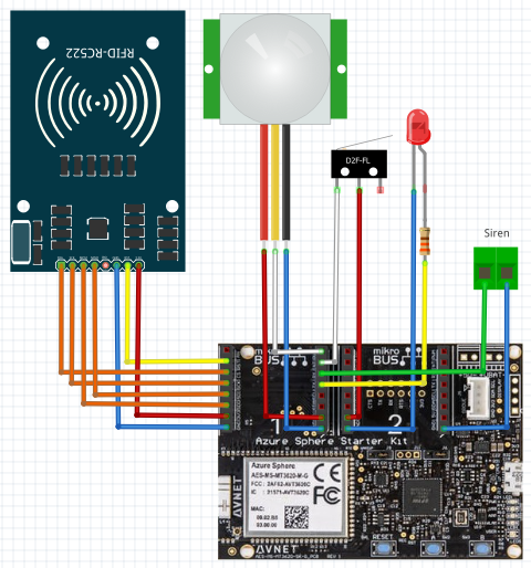
Avnet's MT3620 comes with two ClickBoard slots, a I2C slot, a Grove connector and some useful sensors. In this example, I am connecting the necessary components directly to ClickBoard connectors. Pinout and connections are shown in the schematics section. Remember that MT3620 has 3.3V logic level, so we are going to power everything with that voltage.
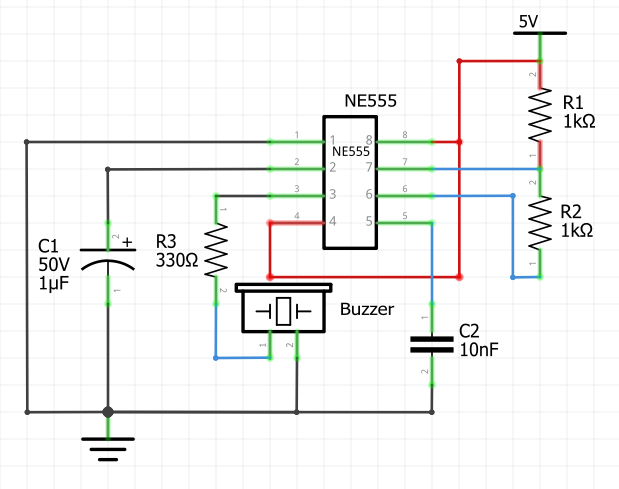
The siren module is a board I developed for another project and can be replaced by any other sound module. For the sake of completeness, I have attached the diagram of the one used in the project.
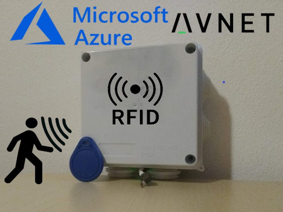
I decided to host the components inside an IP65 junction box in order to guarantee solidity to the system. A ø5mm hole on one side is housing the LED. You need to remove two plastic caps: one to house the PIR sensor and the other to wire a USB power cord. RFID reader is glued below the lid. Place cardboard sheets between components to to guarantee electrical insulation. As said before, power is taken from a USB transformer, not the best solution for an alarm central, but this is a proof-of-concept.
- Connect the RFID-RC522 reader to the SPI interface.
- Connect a LED to PIN26 and GND.
- Connect PIR to PIN0 and GND.
- Connect a limit switch to PIN2 and 3.3V.
- Connect siren module to PIN28 and GND.
Once everything is connected and the board is connected to PC, click on "Remote GDB Debugger" in Visual Studio. The board will be programmed and the software will start. Check that telemetry data is being sent to IoT Central.


Comments