3D projection is any method of mapping three-dimensional points to a two-dimensional plane. As most current methods for displaying graphical data are based on planar two-dimensional media, the use of this type of projection is widespread, especially in computer graphics and engineering.
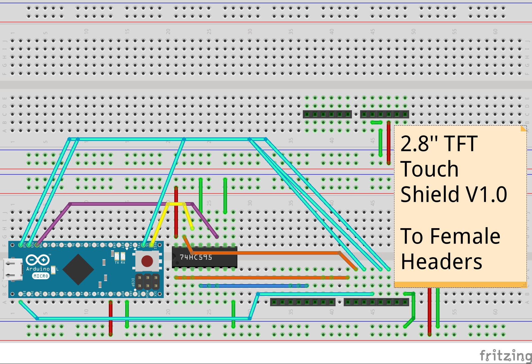
3D axonometric projection on Arduino Micro 8-bit and TFT touch shield change of projection is made using the touch screen.
3D axonometric projection on ESPDUINO-32 3-2bit and TFT touch shield change of projection and rotation is made using a web client.
Axonometric projection is a type of parallel projection used for creating a pictorial drawing of an object, where the object is rotated along one or more of its axes relative to the plane of projection.
There are three main types of axonometric projection: isometric, dimetric, and trimetric projection.
"Axonometric" means "to measure along axes". Axonometric projection shows an image of an object as viewed from a skew direction in order to reveal more than one side in the same picture. Whereas the term orthographic is sometimes reserved specifically for depictions of objects where the axis or plane of the object is parallel with the projection plane, in axonometric projection the plane or axis of the object is always drawn not parallel to the projection plane.
With axonometric projections the scale of distant features is the same as for near features, so such pictures will look distorted, as it is not how our eyes or photography work. This distortion is especially evident if the object to view is mostly composed of rectangular features. Despite this limitation, axonometric projection can be useful for purposes of illustration.
WINDOW-TO-VIEWPORT COORDINATE TRANSFORMATION.
A world-coordinate area selected for display is called a window. An area on a display device to which a window is mapped is called a viewport. The window defines what is to be viewed; the viewport defines where it is to be displayed.
Figure illustrates
the window-to-viewport mapping. A point at position (xw, yw) in the window is mapped into position (xv, yv) in the associated viewport. To maintain the same relative placement in the viewport as in the window, we require that
xv - xvmin 	= 	 xw - xwmin
------------  		--------------
xvmax - xvmin  		 xwmax - xwmin

yv - yvmin	= 	 yw - ywmin
-------------  		--------------
yvmax - yvmin  		 ywmax - ywmin
Solving these expressions for the viewport position (xv, yv), we have Ecuation A
xv = xvmin + (xw - xwmin)sx
yv = yvmin + (yw - ywmin)sy
where the scaling factors are
sx = xvmax - xvmin
     --------------
     xwmax - xwmin

sx = yvmax - yvmin
     --------------
     ywmax - ywmin
Equations A can also be derived with a set of transformations that converts the window area into the viewport area.
This conversion is performed with the following sequence of transformations:
1. Perform a scaling transformation using a fixed-point position of (xwmin, ywmin) that scales the window area to the size of the viewport.
2. Translate the scaled window area to the position of the viewport.
Relative proportions of objects are maintained if the scaling factors are the same (sx = sy).
Otherwise, world objects will be stretched or contracted in either the x or y direction when displayed on the output device.


_PnKPri8a6q.jpg?auto=compress%2Cformat&w=48&h=48&fit=fill&bg=ffffff)


Comments
Please log in or sign up to comment.