


_lhotzTTj9G.jpg?auto=compress%2Cformat&w=900&h=675&fit=min)
Hardware components | ||||||
 |
| × | 1 | |||
 |
| × | 2 | |||
 |
| × | 1 | |||
 |
| × | 1 | |||
 |
| × | 1 | |||
 |
| × | 2 | |||
 |
| × | 2 | |||
There is a lack of step wise approach towards starting electronics especially for the first timers. So I created a blog and tutorials especially for the beginners, and most of the tutorials are on breadboard. So that the doer, can completely understand the hardware. With detailed step wise approach, I made sure that the tutorial is easy for anyone. The whole series can be found here : go8051.com
So here is the step wise tutorial:
Materials Required for 8051 basic breadboarding tutorial
Once again we will check out the materials which are needed for the tutorial Now tally your material and get ready.
Bill of material:
1. Keep your breadboard straight no matter which is pointing in which direction. Just make sure that once you have decided the side, you should not change it as it will be hectic for you to operate. We will use red wire for positive lines and black wire for ground lines. Make the connection of the positive input lines as follows
2. Now next step is to pin up ground wires. Connect as shown in following image.
3. Now lets finish off with the third line which will be output line from where +5v will be regulated all over the breadboard.
4. The breadboard is divided into two regions. Now lets supply GND in both the regions.
5. Complete the setup with also connecting red lines in both the regions
6. Join the middle part for both ground and +5v lines which will complete the power supply into the breadboard.
7. Connect the ground lines to complete the wiring setup on the breadboard.
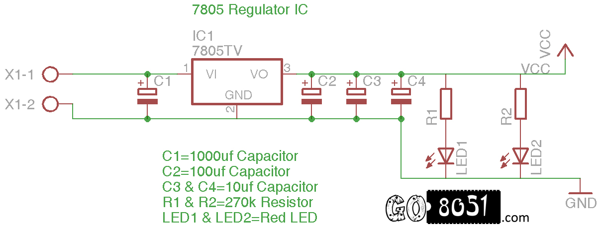
8. Now place the 7805 regulator in the following manner. Be careful while placing and don't place it wrongly as it would heat the 7805 regulator IC and would damage it.
9. After Placing, it would somewhat look like the following image.
10. Place the 100uf Capacitor between the +ve and -ve lines i.e just between the +5v Output voltage and the ground of the regulator.
11. Now similarly place a 1000uf capacitor in between the input voltage and the ground. This will act as a global storage for power supply i.e when the battery is removed it will make sure that power is not gone instantly.
12. Now Place the 10uf capacitor on the left part of breadboard between -ve and +ve lines. See the below image for reference
13. Similarly, Now place the 10uf capacitor on the other side also. It would look like the following image.
14. Now, The setup is almost complete. To indicate that the there is powersupply running through out the breadboard, we will place an indicator i.e. LED bulb which will show that there is power supply in both the lines. The cathode of led on -ve lines and positive on the breadboard main line.
15. Now, we will use a 270 Ohm resistor to limit the power supply for the LED bulb. Since, it would get damage if the voltage is more. Connect the anode of LED to +ve side of breadboard.
16. The setup will look like this:
l
17. Do the same thing on the other side of the breadboard. Refer the following image.
18. Now lets check whether the circuit is working or not. Put on the +ve wire of the battery snapper in the Input of 7805 Regulator IC. Refer the following image for assistance.
19. Now put the Black wire in the gnd of 7805 regulator as following image.
20. It would look like the following image
21. Now connect a 9v battery and if your connections are OK then the LED at both the ends will glow up like the following image.

Comments
Please log in or sign up to comment.