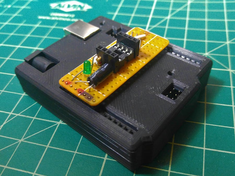
Build an Arduino UNO shield to program 8 pin ATtiny microcontroller! We'll take advantage of the ATmega16U2 on the UNO to program an ATting13A.
Connections- ATtiny pin 1 (PB5) <--> Arduino pin D10
- ATtiny pin 2 (PB3) <--> x
- ATtiny pin 3 (PB4) <--> x
- ATtiny pin 4 (GND) <--> Arduino GND
- ATtiny pin 5 (PB0) <--> Arduino pin D11
- ATtiny pin 6 (PB1) <--> Arduino pin D12
- ATtiny pin 7 (PB2) <--> Arduino pin D13
- ATtiny pin 8 (Vcc) <--> Arduino +5V
Follow the pinout diagram below for additional reference.
Below is a collection of photos as I progressed through the build of the shield.
AssemblyI cut down stripboard for this build.
Use a DIP8 socket for the ATtiny to quick connect/disconnect. The rows of female headers is optional.
My board was single sided, which forced me to get creative with soldering the pins that go into the Arduino UNO.
Add a 10uF electrolytic capacitor between the Arduino's Reset pin and Ground.
I installed an LED with a series resistor on pin 2 aka PB3/D3.
If using a strip board, remember to cut traces where necessary.
1. Arduino as ISP
- Plug in the UNO, select the correct COM port and board.
- Arduino IDE >
File>Examples>ArduinoISP>ArduinoISP>Upload
2. ATtiny Hardware Package Installation
File>Preferences>Additional Boards Manager URL> Paste:
https://raw.githubusercontent.com/sleemanj/optiboot/master/dists/package_gogo_diy_attiny_index.jsonOKTools>Board>Boards Manager> Find "DIY ATtiny" >Install
3. Configure Settings
- Make sure your settings match the image below. I used an ATtiny13A.
4. Test Code
- Download the "ATtiny Blink" sketch provided at the bottom of the guide and upload it.
- Observe if LED toggles every second.
Congratulations! The shield is complete. If you wish to print the enclosure used on the UNO, you can find it here (Note that it was designed around genuine boards without multiple rows of header pins). Happy tinkering.


_ztBMuBhMHo.jpg?auto=compress%2Cformat&w=48&h=48&fit=fill&bg=ffffff)


Comments
Please log in or sign up to comment.