


Hardware components | ||||||
 |
| × | 1 | |||
In present generation, vehicles being reported stolen is increasing at an alarmingly high rate. There are thousands of cases of auto theft each year making it one of the nation’s major property crimes. Hence, an access control system forms a vital link in the security chain. This microcontroller based vehicle lock presented here is an access control system that allows only the specified user to access the vehicle. The password protected vehicle access system comprises of a touch screen module and an LCD display which is fixed in the vehicle. The password can be entered using the touch screen. The control circuit is able to actuate one of two choices. First choice, if the entered password is true, the vehicle’s lock is deactivated and the LCD display works as a digital speedometer. Second choice, if the entered password is wrong, then the user is able to re-enter for maximum of three error entries, after that the alarm system is activated and the system will be locked for ten minutes. It also sends a message to the user’s cell phone to alert him/her using GSM module.
A.PowerSupply
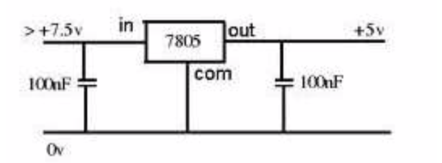
The system requires a regulated +5V supply for the entire operation. This can be delivered from a 9V dc battery given to IC7805, a positive series voltage regulator. This regulator provides stable 5 V DC output against large fluctuations in in/out voltage and load. It also has internal protection circuit which “brown-out” the device when overloaded. It is a three terminal IC. Pin 1 is the input pin, Pin 2 is the ground and Pin 3 is output pin
B.Microcontroller: PIC16F877A
Microcontroller PIC16F877A is used to make the system function as per the requirement. It controls the entire activity of the system.The program for the entire system will be stored in the microcontroller. This system uses 16F877A as the microcontroller because it has low cost, reliable, easy to use and capable of performing a wide range of tasks. The PIC16F877A features256 bytes of EEPROM data memory, self-programming, an LCD, 2 Comparators, 8channels of 10-bit Analogue -to-Digital converter, 2 capture/compare/PWM functions, the synchronous serial port can be configured as either 3-wireSerial Peripheral Interface for the 2-wire Inter-Integrated Circuit bus and aUniversal Asynchronous Receiver Transmitter. All of these features make it ideal for more advanced level A/D applications in automotive, industrial, appliances and consumer applications. So we have utilized the MICROCHIP PIC16F877A microcontroller in the project
C.Display Section
The system uses a 16x2 LCD module to function as a digital speedometer when the correct password is entered. A 16x2 LCD means it can display 16 characters per line and there are 2 such lines. In this LCD, each character is displayed in 5x7 pixel matrix. This LCD has two registers, namely, Command and Data.
D.Buzzer and Relay Section
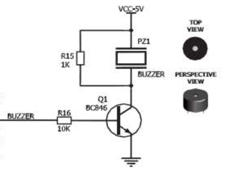
A +5V dc buzzer is used to raise an alarm when three times incorrect entries are made. This has been interfaced with the microcontroller for its proper functioning. Also, a relay is an electronic switch which allows one circuit to switch another ON/OFF. This is used to move the system in lock state in the case of incorrect password entries. Since the buzzer and relay requires more current than provided by the microcontroller, a method of current amplification is needed which can be obtained by using a darlington pair transistor, i.e., two transistors linked together, one with high gain and other with high power rating. Hence, TIP122, npn darlington transistor is used which gives high gain and high current capability and can easily drive the buzzer and relay.
E.Touch Screen Module
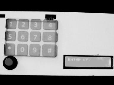
A touch panel is a thin, self-adhesive transparent panel placed over the screen of a graphic LCD. This is used to enter the password in the system necessary for accessing the vehicle. Resistive LCD touch screen monitors rely on a touch overlay, which is composed of a flexible top layer and a rigid bottom layer separated by insulating dots, attached to a touch screen controller. The inside surface of each of the two layers is coated with a transparent metal oxide coating (ITO) that facilitates a gradient across each layer when voltage is applied. Pressing the flexible top sheet creates electrical contact between the resistive layers, producing a switch closing in the circuit. The control electronics alternate voltage between the layers and pass the resulting X and Y touch coordinates to the touch screen controller. The touch screen controller data is then passed on to the computer operating system for processing. Resistive Touch Screens are composed of two flexible sheets coated with a resistive material and separated by an air gap or microdots. When contact is made to the surface of the Touch Screens, the two sheets are pressed together, registering the precise location of the touch. Because the TouchScreens senses input from contact with nearly any object (finger, stylus/pen, palm) resistive Touch Screens are a type of "passive" technology.
The following setup is required to determine the X coordinate:
TopLeft: GND Top Right: +5V
BottomLower: To A/D converter (X co-ordinate)
BottomUpper: OFF
Similarly, to determine the Y co-ordinate, the following setup should be made:
Top Left: To A/D converter (Y co-ordinate)
Top Right: OFF Bottom Lower: GND
Bottom Upper: +5V
F.GSMModule
GSM (Global System for Mobile communication) is a digital mobile telephony system which uses a variation of time division multiple access(TDMA) and is the most widely used of the three digital wireless telephony technologies (TDMA, GSM, and CDMA). GSM digitizes and compresses data, then sends it down a channel with two other streams of user data, each in its own time slot. It operates at either the 900 MHz or 1800 MHz frequency band The GSM module used in this project is SIM300. SIM300 is controlled by the microcontroller using AT commands send via serial communication. The controller operates at TTL logic level (0-5V) whereas the serial communication in GSM works on RS232 standards (- 25 V to + 25V). This makes it difficult to establish a direct link between them to communicate with each other.. TheMAX232 IC is used to convert the TTL/CMOS logic levels to RS232 logic levels during serial communication of microcontrollers with GSM module.
The AT commands used in this project are :
AT+CMGF - This command is used to set the SMS mode. Either text or PDU mode can be selected by assigning 1 or 0in the command.
SYNTAX: AT+CMGF=<mode>
0: for PDU mode
1: for text mode
AT+CMGS - This command is used to send a SMS message to a phone number.
SYNTAX: AT+CMGS= serial number of message to be send.
G.Digital Speedometer
The 3144 is an integrated Hall Effect latched sensor.This is used for incorporating digital speedometer in the project. Hall effect is the phenomenon by which an electric field is generated when a magnetic field is applied perpendicular to the current carrying conductor. As the wheel rotates, the sensor senses the magnetic field once in each rotation. This count is given to a counter in rotation per second. Speed is calculated by multiplying the number of rotations per second with the circumference of the wheel. This can be then converted into kms per hour.
III. Software DesignThe advantages of this system include keyless access to the vehicle. Also as it incorporates a touch screen module, it eliminates the need for a keyboard input, resulting in a cheaper and a lighter overall design.Soft keypad also makes it easier to enter and edit data quickly. Another advantage of a touch screen display is that it is usually much quicker to navigate around the screen than using a keyboard or a mouse type inputs. Hence, provides the speed of making a correct selection
V. ConclusionPasswordProtected Vehicle Access System is a project based on microcontroller, due to which hardware requirement is reduced. The hardware implementation and its operation is functioning accordingly and smoothly following the procedure. Modifying the software will be enough for future enhancement of our project. In a dynamic scenario wherein the breed and nature of real time systems are subjected to promising changes, this project is aimed at adding the fundamental functionality of interfacing them with varying ambience enabling them to be stable and reliable.


Comments
Please log in or sign up to comment.