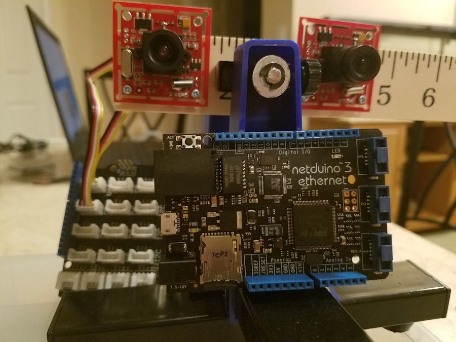
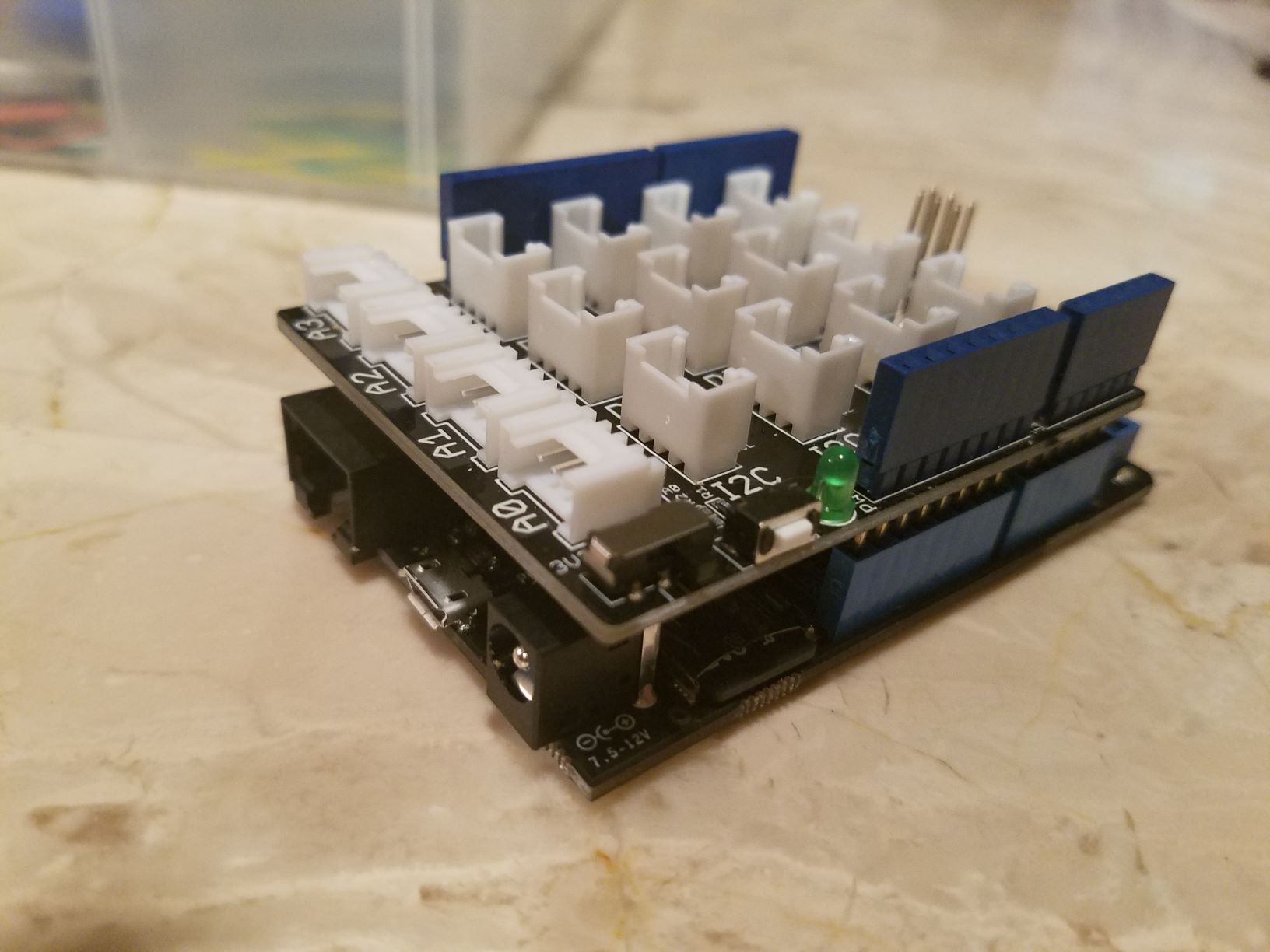
Stereo vision has been one of the most complicated and resource intense process's to extract 3D information. The Netduino 3 Ethernet board, equipped with a Cortex-M4 168 Mhz microprocessor, is capable of intense execution for small amounts of image data.
The board also comes with 4 UART ports ready for use and is perfect for serial communication cameras.
We were able to support the OV528 protocol to communicate with two serial cameras and acquire two continuous photos of still objects. In the near future we will apply one of the stereo vision algorithms to extract the 3D information out of the acquired images.
This system is split into two parts: Part one of the project will mange the hardware and acquire the stereo images on demand, and part two of the project will then calculate internally the 3D coordinates of the object snapped.
ComponentsA stereo vision system consist of a couple digital cameras with known horizontal displacement and symmetrical alignment. These digital cameras simultaneously acquire images and calculates the 3D spatial information.
We attached the two cameras to a wooden ruler to test the different horizontal displacement between the cameras and how it affects the 3D calculated measurements. Currently the only check we've done, is with the cameras separated by 3 inches from their focal axis (lens center).
The system consists of two serial cameras capable of snapping images up to 640x480. We choose to select a resolution of 320x240, to make processing the data easier. The smaller the size, the less processing resource is required.
Currently, the recording process is sequential: sets the camera for capture, send the snap command, and finally read the image buffer to the application. This process is done for camera 1 and then repeat it for camera 2.
The image data is saved in the SD card from the Netduino 3.
if (_button.Read())
           {
               //Record image from camera 1
               Set4Capture(Camera1);
               Snap(Camera1);
               GetImage(Camera1);
               //Record image from camera 2
               Set4Capture(Camera2);
               Snap(Camera2);
               GetImage(Camera2);
           }
Please note that we are not aiming for real time 3D calculation and display, but more of an object modeling for 3D scaning.
UART CommunicationThe Netduino 3 supports up to 4 UART channels. We use UART COM1 and UART COM2 to connect the cameras.
The .NET MicroFramework supports UART devices by defining an event callback function that will be triggered when the system receives information thru one of the active ports.
//Set event callback function
       Camera2.DataReceived += SerialDataReceived;
       Camera1.DataReceived += SerialDataReceived;
The event function is defined as below. Both cameras calls the same event function and internally checks to see which instance made the call.
The received data is stored on a local memory array and then moved to a global variable so we can access it. The amount of data received is also saved into a global variable.
static void SerialDataReceived(object sender, SerialDataReceivedEventArgs e)
   {
       if ((e.EventType == SerialData.Chars) && (sender == Camera1))
       {
           const int BUFFER_SIZE = 1024;
           byte[] buffer = new byte[BUFFER_SIZE];
           int amount = ((SerialPort)sender).Read(buffer, 0, BUFFER_SIZE);
           if (amount > 0)
           {
               for (int index = 0; index < amount; index++)
               {
                   messageFromCam1[index] = buffer[index];
               }
               dataRead1 = true;
               dataSize1 = amount;
           }
       }
       else if ((e.EventType == SerialData.Chars) && (sender == Camera2))
       {
           const int BUFFER_SIZE = 1024;
           byte[] buffer = new byte[BUFFER_SIZE];
           int amount = ((SerialPort)sender).Read(buffer, 0, BUFFER_SIZE);
           if (amount > 0)
           {
               for (int index = 0; index < amount; index++)
               {
                   messageFromCam1[index] = buffer[index];
               }
               dataRead1 = true;
               dataSize1 = amount;
           }
       }
   }
The synchronization of the events after sending a command and waiting for the answer, is still a challenge we have yet to overcome. We will be looking into semaphores or critical sections. The complication is due to the fact that the board implements a round-robin scheduler that adds infinite loops while waiting for a variable to change state. This might deadlock the process and set the event process into a starvation mode. We will report on part two of the project as soon as we learn how to synchronize the events.
In the meantime, we approach the synchronization issue by brute force. In other words if we do not receive the acknowledgement stream we are expecting, then we send the command again, and again until the correct response is received. You can see it in the below code.
           while (true)
           {
               clearBuffer(camDevice);
               sendCmd(camDevice, cmd, 6);
               cmdRet = readReply(camDevice, resp, ref dS2R);
               if (!cmdRet && dS2R < 6) continue;
               if (resp[0] == 0xaa && resp[1] == (0x0e | cameraAddr) && resp[2] == 0x0d && resp[4] == 0 && resp[5] == 0)
               {
                   if (dS2R == 12)
                   {
                       if (resp[6] == 0xaa && resp[7] == (0x0d | cameraAddr) && resp[8] == 0 && resp[9] == 0 && resp[10] == 0 && resp[11] == 0)
                           break;
                   }
               }
           }
Note, that we are using an infinite loop. Send the initialization command, check if the acknowledgement response has being received and if it's not the expected response, repeat the process again.
The camera clears the command buffer after it processes a command, therefore the camera is ready for a new command as soon as it processes the previous one.
This method works out eventually, but it could be faster.
Camera Protocol OV528The below table shows the commands available to program the serial camera using the OV528 protocol. This protocol is based on commands specified in sextuplets of bytes. Depending on the command sent, an acknowledgement is sent back of the same size or double.
The commands are sent thru the UART port and synchronizes to receive the acknowledgement.
Our configuration sets the cameras to acquire a resolution of 320x240 8 bit color. The protocol is really simple and straight forward.
ExperimentWe used a single horizontal displacement of 3 inches from the cameras center field of view. Two still objects were used to acquire stereo images, and the system setup is shown in the following snapshot.
The stereo images acquired from the system were not perfectly aligned, however it was a good starting point to test the robustness of a possible stereo vision algorithm that we will be implementing on the next stage of the project.
On part two of the project we will
- Improve command synchronization
- Calculate depth map internally
- Allow selection of different resolutions
- Implement a simple preview mode to align properly the cameras.
Thank you for reading thru the project. If you would like to know more about our activities, please visit our web page www.vistelilabs.com. We hope to meet you at the 2018 World Maker Faire, we will be there showcasing.


Comments
Please log in or sign up to comment.