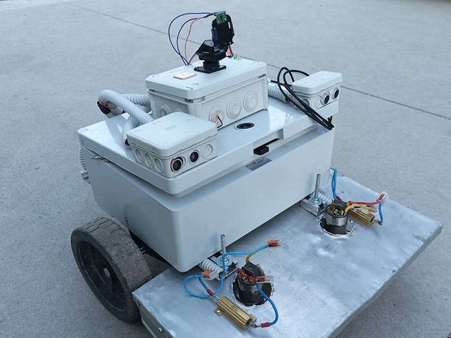
What do you do, if you have a garden to mow, some spare Arduino devices and enthusiasm forembedded and control systems :) You build an Autonomous Lawn mower.
If you are not fond of any of these and just want to get the garden mowed, then buy acommercial product, it is much more faster and easier, than building, codingand testing a system like this.
Mechanical characteristics and wiringI built the mechanical parts of the mower from an old control cabinet. The PLC had to be removed and the cabinet itself could be used. To hold the motors an aluminum profile is fixed onto the bottom of the cabinet. For protecting the motors from external mechanical injuries, I bended a shield over them from a metallic house of an old PC.
The cabinet holds the batteries, the Due with the Ethernet shield, the relay for starting the mower motors and the current measurement PCB. It is a little overcrowded, maybe next time I will use a bigger cabinet :)
Atop thecontrol cabinet there are some small connection boxes. One is holding theDMW100, the GPS and the LIDAR sensor. The smallest one only holds an HCS04, while the another one holds an HCS04 and an Arduino Nano and MCP2515.
The cablings(power supply, Serial, CAN and I2C) are protected from external effects or injuries by putting them into plastic tubes.
Onboard Control systemThe main controller, or as I call it, the movement controller is an Arduino Due. It is communicating over CAN, Serial and I2C. I like using them, because I think buses gives the advantage of a reduced amount of cablings.
Onboard controllers:
The onboardpower supply system:
For the Nanos and the Pro Mini I simply use the loop function, but on the Due, because it has to solve a really complex control algorithm and communication, I use FreeRTOS with several tasks.
https://github.com/bdmihai/DueFreeRTOS
UsonicThe ultrasonic sensors are used to detect if anything is ahead of the mower. It just sends the actual distance to the movement controller over CAN.
LIDARIf the ultrasonic sensor has detected anything ahead, the movement controller shall activate the LIDAR sensor. It sends the actual measured distance and the angle of the servos to the movement controller. Form this data the movement controller can alter the actual movement for avoiding the object ahead.
MPU6050The Movement controller is reading the values of the MPU6050, to stop the movement and the mowing too, in case of overturning.
Navigation idea and the Movement of the MowerFew cm navigation is reached by the usage of DMW1000s. The TAG, which is on the mower measures its distance to the Anchors. From the distance, x and y coordinate is counted.
The Anchors are using Arduino Pro Minis, which are communicating with the DWM1000s over SPI.
The powersupply of the Anchors:
I put the Anchors into small boxes:
The usedlibrary for the DWM100s:https://github.com/thotro/arduino-dw1000
Navigation ideaThe Tag is measuring the distance to the different Anchors.
Now, this shall be put into a coordinate system, the only trick is, the Anchor A shall be at the 0.0 coordinate. Additionally the mower shall know the distance between the A and B, B and C, A and C anchor’s.
If this isdone, it gives the following triangle:
From the triangle, using the cosine’s thesis the Alpha angle can be counted, and from the alpha angle the x and y coordinate can be counted:
Now, we have a coordinate system in which the mower can identified.
Identifying the perimeter.
The mower shall know, which area shall be cut. To do that, the perimeter shall be teached. If the perimeter teaching is activated the, the mower can be controlled manually from any smart phone, via the Bluetooth Arduino application. Based on the encoder signal provided by the motor, the perimeter’scoordinates are saved onto the SD card.
Since the mower uses a small battery, it shall mow a given point only once. To enreach that the when the automatic function is activated, the following happens:
1.Designing the route
To make it as simple as possible, the mower will cover the area parallelto the y axis. Fort he designing the area it takes the length and the width ofmower in consideration.
Here is how the output will look like:
After the planning of the route, movement starts immediately.
2.Cutting the perimeter
First the mower will cut the perimeter. It is done by following/reaching the saved perimeter points from the SD card.
3.Cutting the planned routes
After the last perimeter point has been reached the mower will start the execution of the planned routes. When a line is done, it searches the closest one and starts executing it.
When all the planned routes are executed, then the automatic function becomes deactivated.
Turning the mower into the right directionThe mower can be anywhere, okay within the range of the DWM1000, before activating the automatic function. After activation, the mower moves in a straight line for 5s, to get the previous and actual position. It is necessary to count the right SP for the motors for the proper turn.
Actually it is solved with a simple coordinate math and vectors.
Based onthe Alpha and Beta angle, and their position in the quarters in the coordinate system, the SP can be counted.
After some testing I am still struggling withthe DWM1000.


_3u05Tpwasz.png?auto=compress%2Cformat&w=40&h=40&fit=fillmax&bg=fff&dpr=2)

Comments
Please log in or sign up to comment.