


Hardware components | ||||||
 |
| × | 1 | |||
 |
| × | 1 | |||
Software apps and online services | ||||||
| ||||||
| ||||||
For building the joystick with physical buttons and gliders we use the project in Part1 : Nucleo32 STM32L432KC board with USB interface.
All we have to do is to add the analog and digital IO to the design. Analog on port PA3 and PA4 (arduino A2 and A3 ports), Digital to PA5 and PA6 (Arduino A4 and A5), see schematic
CubeMXThis is done in CubeMX, adding two more analog IO, single ended. We use 8 bit as that is enough resolution and use the polling-mechanism to check the Analog converted data. (Discontinued conversion, 2 channels, triggered by software, no DMA). The 'Rank' of ADC channels gives the sequence of conversion, be sure to setup the two channels here.
We connect two 10Kohm Potentio-meters to 3.3V and Gnd, and connect the runner to the Analog ports. For the digital buttons assign GPIO with an internal pull-up. Buton press force the IO to ground - see schematics
Generate the project (or load the complete project in CubeIDE), be aware to re-overwrite the saved USB Class descriptior, as they are overwritten once you generate a new Code from CubeMX. Originals are in a zip-file in the HID folder.
0x05, 0x01, // Usage Page ( Generic Desktop controls)
0x09, 0x04, // Usage (Joystick)
0xA1, 0x01, // Collection (Application)
	0xA1, 0x02, // Collection (Logical)
		0x05, 0x01, // Usage Page (Generic Ctrls)
		0x09, 0x30, // Usage X
		0x09, 0x31, // Usage Y
		0x15, 0x81, // Logical Minimum (0)
		0x25, 0x7F, // Logical Maximum (0xfcf)
		0x75, 0x08, // Report Size (8) -> 8 bits (1 byte value)
		0x95, 0x02, // Report Count (2) -> 2x = 2 bytes
		0x81, 0x02, // Input (Data,Var,Abs,...)
		0x05, 0x09, // Usage Page (Button)
		0x09, 0x01, // Usage Button1
		0x09, 0x02, // Usage Button2
		0x15, 0x00, // Logical Minimum (0)
		0x25, 0x01, // Logical Maximum (1)
		0x75, 0x01, // Report Size (1) -> 1 bit
		0x95, 0x02, // Report Count (2) -> 1 value : need to stuff 6 more bits
		0x81, 0x02, // Input (Data,Var,Abs,...)
		0x75, 0x06, // Report Size (6) -> 6 bit
		0x95, 0x01, // Report Count (1) -> 1 value : need to stuff 6 more bits
		0x81, 0x03, // Input (Const,Var,Abs,,,,,) CONSTANT type !!
	 0xC0, // end collection Logical
0xC0, // End Collection => 48 bytes , report 2 bytes for XY and 1byte for buttonsThe USB interface is similar to the one inb Part1, except we added one more button. The USB report stays the same2 bytes Analog value, one Byte value for the button(s) - bit0 and bit1.
For debug purposes there are some text message possible in main(), using sprintf() to a text buffer, send out to uart2 (Virtual comport of the debugger)
The analog values are read by startign the ADC, pollign the data and reading the first value. Second polling will load the second ADC value as setup in the Ranking in CubeMX.
// Start ADC Conversion
HAL_ADC_Start(&hadc1);
HAL_ADC_PollForConversion(&hadc1, 10);  // Poll ADC1 Perihperal & TimeOut = 10mSec
raw = HAL_ADC_GetValue(&hadc1);         // Read The first ADC , this is 32bit value!
 gameHID.JoyX = (int8_t) raw-127; 	// cast to singed int

HAL_ADC_PollForConversion(&hadc1, 10);  // Poll ADC1 Perihperal & TimeOut = 10mSec
raw =  HAL_ADC_GetValue(&hadc1); 	// Read The second ADC Conversion
 gameHID.JoyY = (int8_t) raw-127; 	// cast to singed int
HAL_ADC_Stop(&hadc1);

// READ IO's
raw =   ( ~HAL_GPIO_ReadPin(GPIOA, GPIO_PIN_5) )&0x01;    // bit0
raw +=  ( ~HAL_GPIO_ReadPin(GPIOA, GPIO_PIN_6)<<1 )&0x02; // bit1
 gameHID.JoyB1 = (uint8_t) raw;

// Send HID report
USBD_HID_SendReport(&hUsbDeviceFS, (uint8_t*) &gameHID, sizeof(struct gameHID_t));
Compile the project, program the Nucleo or start the debugger:
For problems, or tips&tricks see Part1
Part3: Build an extra Joggle for my iRacing wheel !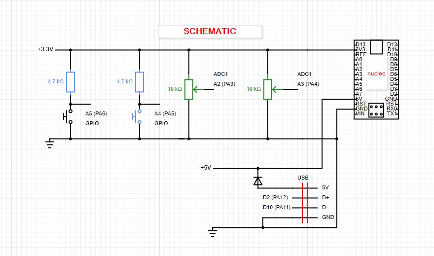


Comments
Please log in or sign up to comment.